Make your next project wireless!
Designed by:
Colin "MrSwirlyEyes" Keef
The HM-10 Bluetooth 4.0 BLE module is a low power, low throughput, and inexpensive wireless device. In this tutorial, we will demonstrate how to use the HM-10 Bluetooth 4.0 BLE module. We will go through the process of programming and pairing two HM-10 modules to connect to each other. Once paired, we will be able to communicate between two microcontrollers (i.e. Arduino UNO) over the air using the HM-10 modules.
We will use two communicate between two HM-10 modules using two techniques. The first is one-way communication. That is, one Arduino + HM-10 pair will purely transmit to the second Arduino + HM-10 pair. The second Arduino + HM-10 pair will be purely receiving from the first Arduino + HM-10 pair. Then, we will communicate between the two pairs simultaneously. The first pair will both transmit and receive from the second pair; and the second pair will receive and transmit from the first pair.
| DEVICE | VENDOR URL | QUANTITY | NOTES |
|---|---|---|---|
| Arduino UNO R3 | Digikey | 2 | May use other variants, but may need minor changes to code. |
| USB Cable (A Male to B Male) | Digikey | 2 | |
| Bluetooth 4.0 HM-10 BLE Module | Amazon | 2 | |
| [Optional] RES 1K OHM 1/4W 5% AXIAL | Digikey | 2 | Optional for the voltage divider to the bluetooth hm-10 |
| [Optional] RES 2K OHM 1/4W 5% AXIAL | Digikey | 2 | Optional for the voltage divider to the bluetooth hm-10 |
| Breadboard (small) | Digikey | 2 | Used for prototyping. |
| Jumper Wire M/M 6 (20pcs) | Digikey | 2 | Used for prototyping. |
To become familiar with the capabilities and limitations of the HM-10 Bluetooth module. Understand how we will communicate between the microcontroller (e.g. Arduino UNO) and the HM-10. Become familiar with UART and a Software UART.
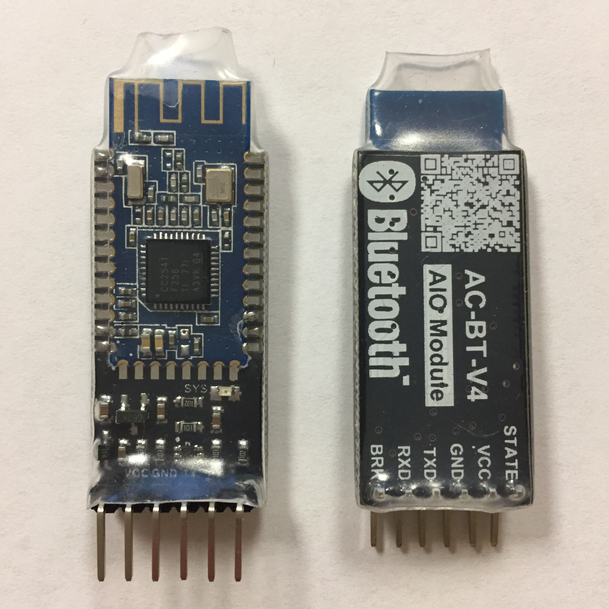
The Bluetooth HM-10 is a wireless bluetooth module based on the TI CC2540/CC2451 RF Transceiver IC. The HM-10 Bluetooth SOC (System on a Chip) is manufactured by Jinan Huamao. Wireless operatation takes place on the 2.4GHz ISM band. Its method of data signal modulating is GFSK (Gaussian Frequency Shift Keying). AT Commands are commands allow us to interface and communicate with the HM-10 module.
The HM-10 is recommended to be powered at 3.3V with an output current of 50mA (very low)! However, extensive testing has proven that operation at 5V works well and is safe for the device. The device can be configured as either a Master or Slave module, making the transceiver extremely flexible.
There is an onboard LED that indicates information about the connection status. When it is blinking, the device is waiting for a connection, but is currently not connected. When a connection is established, the blinking LED turns solid. The LED will remain solid as long as a connection is maintained. When the connection is broken, the LED will return to its blinking state.
There a total of six pins: STATE, VCC, GND, TX, RX, and BRK. We are not concerned with STATE nor BRK. VCC can be powered with 3.3V or 5V. GND is the straight forward GND that, in general, is connected to the common GND of the circuit. As for the TX and RX pins, we discuss these in the next section.
| HM-10 pin | Description |
|---|---|
| VCC | 3.3V-5V |
| GND | Common GND |
| TX | Serial UART transmit pin |
| RX | Serial UART receive pin. May need voltage divider (see note below) |
| STATE | Connection status. LOW for not connected. HIGH for connected |
| BRK | Break connection. When driven LOW, this will break the connection |
When connecting VCC to 5V, you need to use a voltage divider to deliver 3.3V to the HM-10's RX pin.
A Universal Asynchronous Receiver-Transmitter (UART) is a block of circuitry responsible for implementing serial communication. Internally, there is a bus of parallel data lines and control pins managed by the microcontroller. Externally, what the user uses are the simple TX and RX pins of the microcontroller or serial device. Most microcontrollers today come with one or more UARTs. The Arduino UNO's ATMEGA328p has one. The asynchronous aspect means data is transferred without utilizing an external clock signal. This is why we only need 2 pins, TX for transmitting and RX for receiving. In order for this to work well, the microcontroller puts effort into framing and packaging our data in transmission to increase reliability.
The TX and RX pins are labeled with respect to the device itself. Thus the TX of one device is connected to the RX of the reciprocal device and vice-versa. That is, the transmitter of device A is communicating to the receiver of device B, and device B is transmitting to the receiver of device A.
Some microcontrollers do not have a UART (e.g. most ATtinys), however can use a Software UART. Even microcontrollers that do have a hardware UART, but need another serial communication interface can use a Software UART in addition to their dedicated UART. A Software UART is directly controlled by the processor, not as reliable as a dedicated UART, and is processor intensive. We will use a Software UART by utilizing the SoftwareSerial library. We can use the dedicated UART of the Arduino UNO, but when we do it becomes difficult to upload to the Arduino UNO and then using debugging print statements in the Serial Monitor is difficult to sort out.
If you have worked with Arduino a bit, you have probably been exposed to the Serial Monitor. The Serial Monitor is a terminal that connects us to the Arduino UNO. This is convenient for debugging statements, and a more powerful means of communicating between user and Arduino or your computer and the Arduino. Commonly when we use the Serial Monitor, we do not need any extra connections using Arduino pins because we have the USB Cable connected between our computer and the Arduino, which allows for the Serial communication by default. All we need to add is the appropriate code in our program.
Similarly, the HM-10 operates in this way too. We will want to talk to the HM-10 with the Arduino UNO. Our Arduino program will tell the HM-10 what to send or transmit to the receiving device. The way we communicate between Arduino UNO and HM-10 is through UART. We will be explicitly using a Serial UART here with SoftwareSerial, but in the final design of a project, one can use the dedicated UART. As a final note, we will also interface with the HM-10 to program the bluetooth module using UART by addressing AT commands to the device. AT commands will be addressed in more detail in the next section, but the way we address these commands is through serial communication to the HM-10 device.
Connect an HM-10 Bluetooth module to an Arduino UNO. Understand why we need a voltage divider into the HM-10's RX pin.
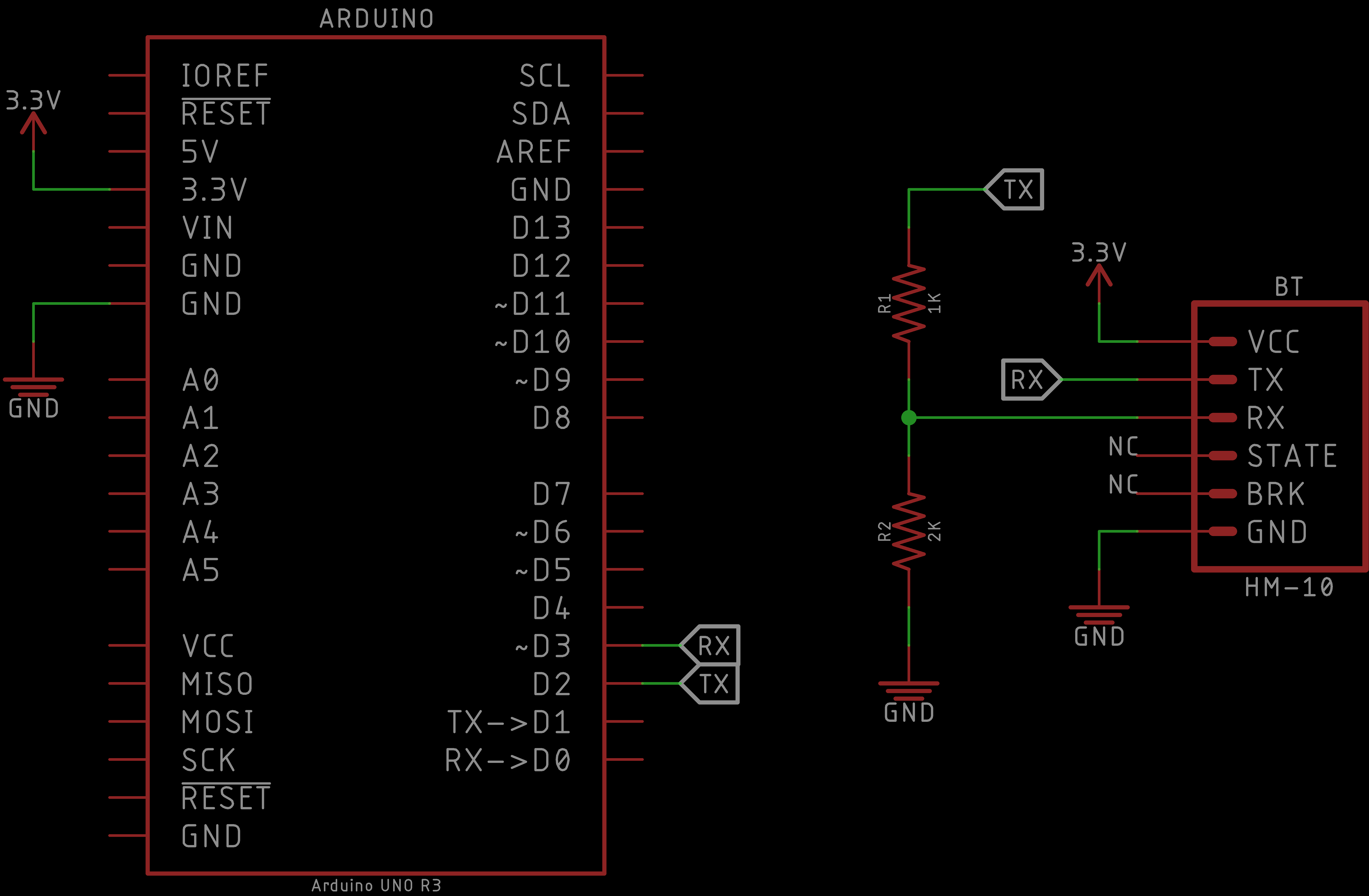
Construct the schematic to connect the Arduino UNO to the Bluetooth HM-10 module. Observe, we have employed a voltage divider from the Arduino's I/O pin to the HM-10's RX pin. This is highly suggsted because we are powering the HM-10 via the 3.3V power rail on the Arduino UNO; however, the Arduino UNO I/O pins are at a 5V logic level. We cannot connect the 5V logic level I/O pin from the Arduino UNO to the HM-10's RX pin and guarantee the HM-10's safety. Thus, we use the voltage divider to protect the HM-10.
You may employ different resistor values for the voltage divider as long as it produces approximately 3.3V as a result.
NC stands for not connected or no connection.
| Arduino UNO | HM-10 Bluetooth |
|---|---|
| 3.3V | VCC |
| GND | GND |
| D3 | TX |
| D2 | RX |
The SoftwareSerial RX pin is connected to the HM-10 TX pin!
The SoftwareSerial TX pin is connected to the HM-10 RX pin through the voltage divider!
You do not need to connect the BRK nor STATE pins on the HM-10. They can be used, but will not be utilized in this tutorial.
If you power on your HM-10 module, the onboard red led should constantly blink - demonstrating that it is not connected (or paired) to any device.
Now we are ready to interface with the HM-10!
Introduce AT commands and how to interface with the HM-10 using AT commands. Collect information from and program the HM-10 module. Pair two HM-10 modules with each other using their respective MAC addresses.
The following table lists several AT Commands. We will use a handful of these to interact with the HM-10 bluetooth module, including how to pair two HM-10 bluetooth modules together to have wireless communication between two Arduino UNOs.
| NAME | SEND | RECEIVE | PARAMETER | DESCRIPTION |
|---|---|---|---|---|
| Test Command | AT | OK | None | Simple test command to see if a response is received. |
| Query Module Name | AT+NAME? | OK+NAME:[para1] | para1: Module name, max length is 12. |
Querys for the HM-10 module name. |
| Set Module Name | AT+NAME[para1] | OK+Set:[para1] | para1: Module name, max length is 12. Default: HMSoft |
Sets the HM-10 module name. |
| Query Module (MAC) Address | AT+ADDR? | OK+ADDR:[para1] | para1: MAC address MAC Address format: 0123456789AF |
Querys for the HM-10 module MAC address. |
| Query Baud Rate | AT+BAUD? | OK+Get:[para1] | para1: Baud rate speed. Default: 0 -> 9600 |
Querys for the HM-10 module's current baud rate. |
| Set Baud Rate | AT+BAUD[para1] | OK+Set:[para1] | para1: Baud rate speed. AT+BAUD0 -> 9600 AT+BAUD1 -> 19200 AT+BAUD2 -> 38400 AT+BAUD3 -> 57600 AT+BAUD4 -> 115200 AT+BAUD5 -> 4800 AT+BAUD6 -> 2400 AT+BAUD7 -> 1200 AT+BAUD8 -> 230400 |
Sets the HM-10 module baud rate. If Baud rate set to 7 (1200), module will not support any AT commands, until PIO0 is pressed, then module will change Baud rate to 9600. |
| Try to connect to a (MAC) address | AT+CON[para1] | OK+CONN:[para2] | para1: MAC address. para2: A, E, F A: Connecting E: Connect error F: Connect fail |
Method to pair one HM-10 module to another HM-10 module or device. |
| Restore all setup to factory setup | AT+RENEW | OK+RENEW | None | Restore HM-10 module to factory settings. |
| Restart module | AT+RESET | OK+RESET | None | Closes any active connection and reboots the HM-10 module. |
| Query Software Version | AT+VERR? AT+VERS? |
Version information | None | Returns the software version of the HM-10 module. |
Do not include the '[' and ']' when sending the AT command.
A complete set of AT commands may be found from the datasheet.
Upload the following code onto your Arduino:
// Serial communication with Bluetooth HM-10
// Uses serial monitor for communication with Bluetooth HM-10
//
// Arduino to HM-10 connections
// Arduino pin 2 (TX) to voltage divider then to HM-10 RX
// Arduino pin 3 to HM-10 TX
// Connect GND from the Arduiono to GND on the HM-10
//
// When a command is entered in to the serial monitor on the computer
// the Arduino will relay the command to the HM-10
// Library to make a Software UART
#include <SoftwareSerial.h>
#define RX 3
#define TX 2
#define BAUDRATE 9600
char c = ' ';
boolean new_line = true;
// Instantiation of a Software UART
SoftwareSerial BTSerial(RX, TX); // (RX, TX)
void setup() {
// Start Serial Monitor for feedback
Serial.begin(BAUDRATE);
// HM-10 default speed in AT command mode
BTSerial.begin(BAUDRATE);
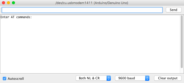
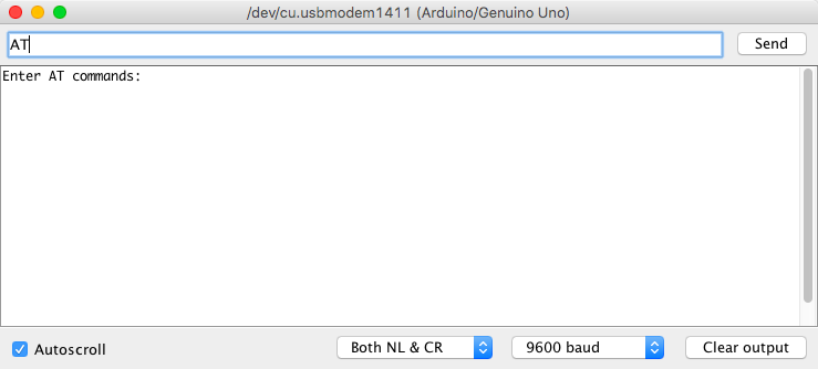
Serial.println("Enter AT commands:");
}
void loop() {
// Keep reading from HM-10 and send to Arduino Serial Monitor
if (BTSerial.available())
Serial.write(BTSerial.read());
// Keep reading from Arduino Serial Monitor and send to HM-10
if (Serial.available()) {
// Read from the Serial buffer (from the user input)
c = Serial.read();
// Do not send newline ('\n') nor carriage return ('\r') characters
if(c != 10 && c != 13)
BTSerial.write(c);
// If a newline ('\n') is true; print newline + prompt symbol; toggle
if (new_line) {
Serial.print("\r\n>");
new_line = false;
}
// Write to the Serial Monitor the bluetooth's response
Serial.write(c);
// If a newline ('\n') is read, toggle
if (c == 10)
new_line = true;
}
}
This program allows us to talk directly to the HM-10. That is, we can open the Serial Monitor and type into its terminal, and the contents of our message will be sent directly to the HM-10 module. The Arduino UNO is the means by which we forward the message to the device. Of course, if we send a garbage (or unknown) command to the HM-10, it will give us a garbage response. In this case, the device will simply not respond with anything (provides no feedback). Using this program we can gather information about our HM-10 module as well as program it.
When opening the Serial Monitor, you should be greeted by the following:
In the Serial Monitor, set the baud rate to: 9600
In the Serial Monitor, set the line ending to: Both NL & CR
When we communicate with the HM-10 we enter our AT command into the Terminal Input, and execute the command by hitting the Enter key or clicking on the Send button in the top-right. This program will await your input, and send it to the HM-10 module. If the command is valid, the device will give an appropriate response.
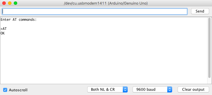
Let us start communicating with the HM-10. We will send the test command AT to the HM-10. In the Terminal Input, the following command, and hit the Enter key.
ATYou should see the following response:
Going further, we will not show the Terminal Input, just the resulting output.
The AT command is essentially a ping or wake-up to the HM-10. Under special cirumstances, it has another function (see datasheet linked in the Resources and References for more details).
If you are not receiving the response shown above, check your hardware setup, and Serial Monitor baud rate and line ending setting.
We are now ready to pair two HM-10 modules together. For each of the bluetooth modules we need to distinguish between them. We will refer to bluetooth module A and bluetooth module B. You may use the same circuit we constructed earlier to do all the work of programming the HM-10 modules. Only one module needs to be powered at a time when performing the pairing procedure (it is a bit different from pairing your phone with a bluetooth device where generally both are active at the same time).
With bluetooth module A we want to first query for the name of the device as follows:
AT+NAME?Next, we want to change the name (so we can keep track which is which in the event we get them mixed up - we recommend you labeling each module with tape and marking to distinguish them). We can set the name of module A:
AT+NAME[NAME_OF_MODULE]You may name the device whatever you like.
We encourage you query for the name of the device again to verify that the name has changed.
In order for us to pair to another HM-10 (module B), we need to determine the MAC address of module B and tell module A to connect to it (we will be operating with auto pairing - which is turned on by default). Similarly, we need to determine the MAC address of module A and tell module B to connect to it. By doing this, both modules will pair to each other and do so instantly when they are powered. With auto pairing enabled, we do not need any code to pair them in our code!
MAC (Media Access Control) address is a hardware identification number that unique identifies the device on a network.
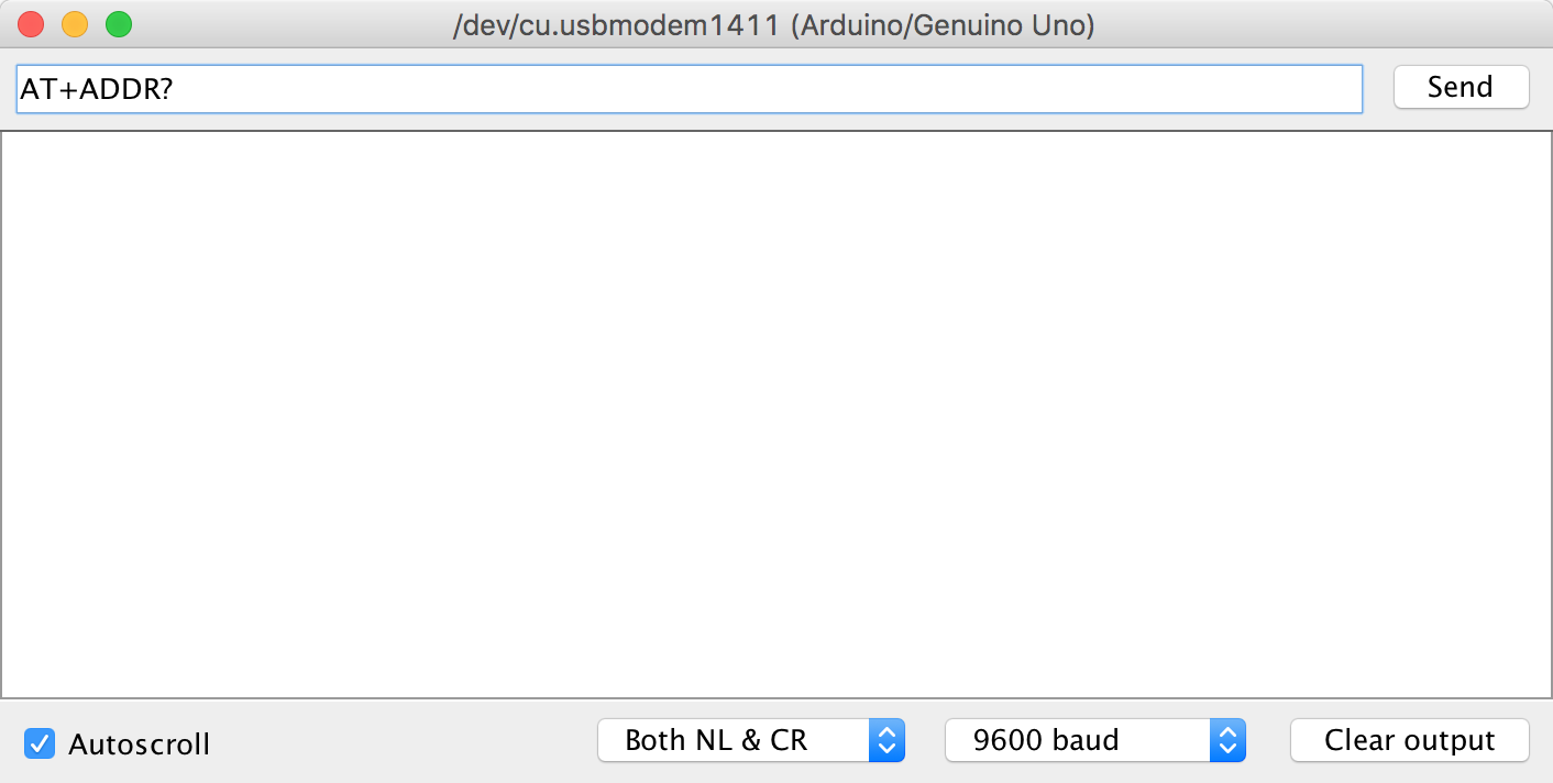
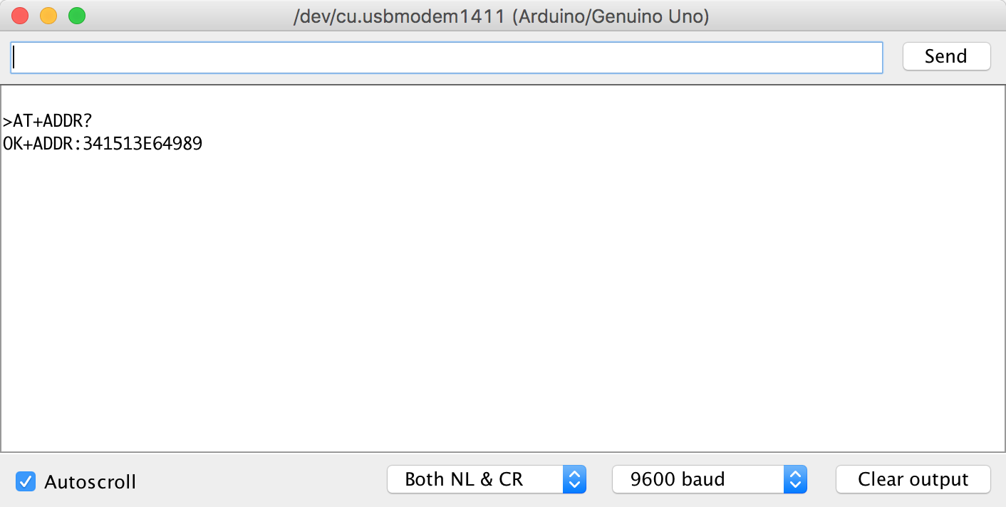
To determine the MAC address of module A, we query for the MAC address of the device:
AT+ADDR?Record the returned MAC address of module A, we need to recall it later!
The MAC address of HM-10 modules will be different, MAC addresses are unique.
Bluetooth modules have roles. Any given bluetooth module acts as either the master (or central) device or the slave (or peripheral) device. By default, HM-10 modules are slave (peripheral) devices. In order for the two bluetooth modules to connect, one of the modules needs to have the role of master (central) which enables the module to scan for slave (peripheral) bluetooth modules.
We will leave module A in its default slave (peripheral) role. But let us convince ourselves with the following command:
AT+ROLE?A role of 0 implies a slave (peripherlal) role.
A role of 1 implies a master (central) role.
As expected, module A is playing the role of slave (peripheral).
We have the information we need from module A. We will return to module A after we program module B with module A's MAC address and receive module B's MAC address.
Swap out module A with module B in your circuit.
With bluetooth module B, follow the same instructions we did earlier with module A to name the device and obtain its MAC address.
Record the returned MAC address of module B, we need to recall it later!
The difference here will be that we need set the role of module B to be the master (central).
If you forget to set the role to master (central) and instead leave both modules as slave (peripheral) devices - the two modules will NOT connect!
Set the role of module B to be the master (central) device:
AT+ROLE[0 or 1]A role of 0 sets the device to be the slave (peripheral) device.
A role of 1 sets the device to be the master (central) device.
A role of 0 implies a slave (peripherlal) role.
A role of 1 implies a master (central) role.
We encourage double-checking that the role has been set with the role query command used earlier.
Since we have the MAC Address of module A, we can program module B to connect to module A as follows:
AT+CON[MAC_ADDRESS]Recall and insert module A's MAC address here!
We are done with module B. It is ready to connect to module A as soon as we program module B to connect to module A.
Swap out module b with module A in your circuit.
Now we have the MAC Address of module B, so we can program module A to connect to module B:
AT+CON[MAC_ADDRESS]Recall and insert module B's MAC address here!
And that is it! You can connect both bluetooth modules to power (you do not need the TX + RX connections) and both modules will instantly connect - denoted by the red LED turning solid.
When the modules are not connected - of if your modules did NOT connect - the HM-10 modules' LED will continuously blink.
When the bluetooth modules are connected (solid red LED), you CANNOT communicate with the HM-10 using AT commands like we have been before. When the module is connected, all AT commands are treated as (transmitted/received) data. The only exception is the AT command which will break the connection. (However, you may notice that as soon as you break the connection, the modules will instantly reconnect again - since we are in auto pairing mode.)
Now that are modules are connected, it is time to communicate wirelessly!
Now we are able to pair two HM-10 modules. If you have been playing around with them, you may have noticed that they will pair as long as both modules are powered. We do not need any connections with TX nor RX. Of course, they are not sending data - but it is an interesting observation that they can be paired and remain in an idle state.
In this module we will demonstrate a trivial example to make sure our HM-10 modules are able to communicate wirelessly. This communication will be one-way, however two-way communication using this same techinque will work (but as we will see, is pretty useless). We will also observe the main pitfall of the communication method we are about to demonstrate. The following modules we will look into one of many techniques in order to make more robust and meaningful method of communication which can be extended to more complex and interesting projects!
Let us get started with our wireless communication hardware setup.
We need to create the same circuit as we had before when programming the HM-10 module for both HM-10 bluetooth modules with two separate Arduinos.
It does not matter in one-way or two-way communication which of the HM-10 modules is the master (central) or slave (peripheral), it is all treated the same when communicating between two Arduino devices.
To make things simple, we will refer to one Arduino and HM-10 bluetooth as Arduino A and (HM-10 bluetooth) Module A, respectively - or Set A. The other set as Arduino B and (HM-10 bluetooth) Module B - or Set B.
With the hardware configured with Set A, we will designate this set as the transmitting device. The example code for Set A to transmit can be copied into your Arduino IDE and uploaded to Arduino A:
// Serial communication with Bluetooth HM-10
// Transmit a trivial string through the Bluetooth HM-10
//
//  Arduino to HM-10 connections
//  Arduino 3.3V or 5V to VCC of HM-10
//  Arduino pin 2 (TX) to voltage divider then to HM-10 RX
//  Arduino pin 3 to HM-10 TX
//  Connect GND from the Arduino to GND on the HM-10
//
// When a command is entered in to the serial monitor on the computer
// the Arduino will relay the command to the HM-10


// Library to make a Software UART
#include <SoftwareSerial.h>

#define RX 3
#define TX 2

SoftwareSerial BTSerial(RX, TX); // (RX, TX)

#define BAUDRATE 9600

String message = "Hello World";

void setup() {

  // Start Serial Monitor for feedback
  Serial.begin(BAUDRATE);

  // HM-10 default speed in AT command mode
  BTSerial.begin(BAUDRATE);
}

void loop() {
  // Send a string for the bluetooth module to transmit
  BTSerial.print(message);

  // Print the same string to the Serial Monitor for feedback
  Serial.println(message);

  delay(1000);
}
Similarly, with the hardware configured with Set B, we will designate this set as the receiving device. The example code for Set B to transmit can be copied into your Arduino IDE and uploaded to Arduino B:
// Basic serial communication with Bluetooth HM-10
// Receive a trivial string through the Bluetooth HM-10
//
//  Arduino to HM-10 connections
//  Arduino 3.3V or 5V to VCC of HM-10
//  Arduino pin 2 (TX) to voltage divider then to HM-10 RX
//  Arduino pin 3 to HM-10 TX
//  Connect GND from the Arduino to GND on the HM-10
//
// When a command is entered in to the serial monitor on the computer
// the Arduino will relay the command to the HM-10


// Library to make a Software UART
#include <SoftwareSerial.h>

#define RX 3
#define TX 2

#define BAUDRATE 9600

char c = ' ';

SoftwareSerial BTSerial(RX, TX); // (RX, TX)

void setup() {

  // Start Serial Monitor for feedback
  Serial.begin(BAUDRATE);

  // HM-10 default speed in AT command mode
  BTSerial.begin(BAUDRATE);
}

void loop() {

  // Keep reading from HM-10 and send to Arduino Serial Monitor
  while(BTSerial.available() > 0) {

    // Read from the bluetooth buffer
    c = BTSerial.read();

    // Write the received bluetooth data to the Serial Monitor
    Serial.println(c);
  }
  Serial.println();
  delay(1000);
}
Let us discuss a bit what the code is doing, and then observe the behavior. The code for the transmitting side, Set A, is setting up two serial interfaces. One is called Serial, which is our typical keyword for the Serial Monitor built into Arduino. The second serial interface called BTSerial is tied to our SoftwareSerial object which creates a virtual serial interface that our HM-10 module is using. In our loop, we are simply printing Hello World to the Serial Monitor (for user - your - feedback), and then sending Hello World wirelessly to Set B over the bluetooth link we have established.
THe code for the receiving side, Set B, establishes the same serial interfaces. In our loop, we have a while loop which has the function BTSerial.available(), which checks if the HM-10 bluetooth module has received data from module A in its buffer. If it has not, we keep looping. If we have received data from set A, then we proceed to read from the buffer. Observe, when we read from the buffer we are reading one character (or byte) at a time into a char variable. Then we print this character (on its own line) to the Serial Monitor (for user - your - feedback).
Great! It works. We are sending data from one Arduino to another wirelessly through our HM-10 modules. This method is acceptable if you want to send 256 unique values (byte values from 0 to 255), which would typically correspond to a single variable, value that would vary, or a command to execute given one of these character codes. However, you are heavily restricted if you want to send two or more pieces of data (e.g. two different sensors). And if these sensors take data that vary across a large range (say > 255), then this method would get complicated. You would probably think of some sort of flag or signal to represent what will be sent next, and when the transmission is done, a signal to signify a complete transmission. Also error, the simple transmission had a large delay (so it was easy to see on the Serial Monitor), but some of the data will miss characters. Error can cause major problems in sending data reliably.
Solving all of these problems gets very complicated. We have a solution that is fast, reliable, and relatively simple. It certainly is not the only way or likely the best method. First, we will start as we did in this module, with one-way communication.
In this module we will demonstrate our method for one-way communication using the HM-10 modules. The method we use here is scalable and easier to receive. Unfortunately, due to limitations of the HM-10 modules and the Arduinos the speeds are not extremely fast, however for many applications this is a wonderous solution.
We want to make a brief mention here that this solution is elegant versus an implementation we realized before. Originally, we had a communication prototcol similar to the last module when we transmitted the 'Hello World' text. The difference was that we added more complexity to our transmission packets that included indicators for when a transmission started and ended (like radio speak when people say 'over'). This worked, however it required tons of code that was dedicated to parsing the received packet. Furthermore, the extensibility was very painful. To send extra data (i.e. another variable), there was several lines of code that had to be added to make the change.
The solution we present is extremely easy to extend and scale. The con to this is the conceptual idea behind how this process works might take awhile to understand and appear cryptic. Regardless, for both solutions the more data we wish to transmit, the more delay we have to add. However, we will be able to do some really powerful stuff with this solution and a good understanding of this technique will go along way in your maker career.
In the last module we sent an entire String of data over the bluetooth with a single line of code. However, when we were reading the data we had to read in the data one byte at a time. Okay, well... We could have used a function called readBytes that can read multiple bytes, but we would need to know how many bytes to read. However, from message to message, you may want to send a different String message with a different length, which corresponds to a different number of bytes, and you would need a code that adapts to this protocol. And this could be a good way of going about your application.
However, we are assuming the data you would normally want to transmit are sensor values and it could be several sensors. Similar, maybe you receive the values on another device and you want to act on it, that is write the values to actuators of the sort so that your sensors are directly controlling your actuators. Maybe you want to send both way in a full duplex and using the idea here will extend to that very easily.
What we will be transmitting and receiving will be a packet. This is a common term in computer networking. The packet we will be sending will hold all the data we wish to communicate to the receiving device. We will illustrate an example that will transmit a few data types: int, float, and byte.
To accomplish this, we will use a C data type: struct. A struct is a tool, or data type, that groups a list of variables under one name in a contiguous block of memory. The block of memory will be as large as the data stored in the struct. So the size of our struct, based on the data types we give it (as listed earlier for example), will be stored contiguously. This is important, because when we transmit the data we only send a stream of bytes. When we receive the transmitted packet, we read them as bytes. The bluetooth module has no idea if we are sending chars, ints, or floats. It only sees bytes. So it is up to You to determine how you are suppose to interpret the data. And the key that makes this easy is the struct! The struct knows how the data, or bytes, needs to be interpreted. So when we receive the message, we just put the raw bytes into this contiguous block of memory. And the struct knows how to interpret it such that we recovery our respective data types appropriately.
So there is a downside to some of this - speed. For the bluetooth modules to transmit and receive reliably, we need some delay. It is very small and barely perceivable. However, as we send more and more data, the delay may have to increase. We seem to get away with about 20-30 ms of delay, which is still extremely fast for most applications.
So let us try it now, the following is the example transmitting code:
// Custom one-way communication with Bluetooth HM-10
// Transmitting data in the form of a struct to receiver
//
// Writes (hardcoded) data to the software UART
//  and prints the transmitted packet


// Library to make a Software UART
#include <SoftwareSerial.h>

#define TX 2
#define RX 3

SoftwareSerial BTSerial(RX, TX); // (RX, TX)

#define BAUDRATE 9600

// Struct to hold the data we want to transmit
struct Packet {
  byte a;
  int b;
  float c;
  int d;
} pkt; // Instantiate a Packet struct

void setup() {
  // Start Serial Monitor for feedback
  Serial.begin(BAUDRATE);

  // HM-10 virtual UART
  BTSerial.begin(BAUDRATE);
}

void loop() {
  // Transmit data via bluetooth
  bluetooth_transmit();

  // Necessary forced delay, if we transmit too fast (no delay)
  //  the error rate increases
  delay(1);
}

// Function responsible for transmitting data over bluetooth
void bluetooth_transmit() {
  // Update data to be transmitted
  pkt.a = 0;
  pkt.b = 255;
  pkt.c = 888.888;
  pkt.d = -100;

  // Write packet data to the bluetooth - and transmit
  BTSerial.write((byte *) & pkt,sizeof(Packet));

  // Print packet (debug)
  print_packet();
}

// Function to print packet data (debug)
void print_packet() {
  Serial.print("TX: (a,b,c,d)=(");
  Serial.print(pkt.a); Serial.print(",");
  Serial.print(pkt.b); Serial.print(",");
  Serial.print(pkt.c); Serial.print(",");
  Serial.print(pkt.d);
  Serial.println(")");
}
There is a lot going on in this transmitting code, so let us walk through it to understand what the code is trying to accomplish, then we will show and discuss the receiving code.
We have defined a C struct named Packet. In this packet, it will contain the data we wish to communicate wirelessly. So for this example, we wish to send four variables: a, b, c, and d. Note their various data types. We call the bluetooth_transmit function which is where all the magic is happening. We make our variable assignments which could have been done outside the function or through another function call. The data can also be dynamic, that is just read from a sensor and assigned to one of the members of the Packet. The write function does all the heavily lifting for us. The line of code looks cryptic, but we disect it now.
In the UART write function we are sending our Packet struct to a buffer to be transmitted. The way we do this is by obtaining the memory address of our Packet (which will point to the beginning contiguous block of memory), hence the &. Then, we type cast this contiguous block of memory into a byte * (byte pointer), which is what the write function is expecting. In the second parameter of the function, we write the number of bytes we are writing to the buffer, this is conveniently done with the sizeof function followed by the data byte (or variable).
Also note worthy is the delay that we have after each transmit. Unfortunately we are using a software UART (not a hardware one), so our speed is slowed. Furthermore, it may be a limitation on our bluetooth module. However, careful tuning of the delay on the transmit (and receive) side must be considered for communication to be fast and reliable. The delay we have implemented is very small, but without any delay (and for no other processing overhead), there may be a high probability of error and getting garbage information.
If you transmit/receive more data, you may have to increase the delay on one or both sides.
Similarly for the receiving code:
// Custom one-way communication with Bluetooth HM-10
// Receiving data in the form of a struct from transmitter
//
// Reads from the software UART and prints the received packet


// Library to make a Software UART
#include <SoftwareSerial.h>

#define RX 3
#define TX 2

#define BAUDRATE 9600

SoftwareSerial BTSerial(RX, TX); // (RX, TX)

// Struct to hold the data we want to receive
struct Packet {
  byte a;
  int b;
  float c;
  int d;
} pkt; // Instantiate a Packet struct

void setup() {
  // Start Serial Monitor for feedback
  Serial.begin(BAUDRATE);

  // HM-10 virtual UART
  BTSerial.begin(BAUDRATE);
}

void loop() {
  // Receive data from the bluetooth
  bluetooth_receive();

  // Necessary forced delay, if we receive too fast (no delay)
  //  the error rate increases
  delay(1);
}

// Function responsible for receiving data over bluetooth
void bluetooth_receive() {
  // Check the software serial buffer for data to read
  if(BTSerial.available() >= sizeof(Packet)) {
    // Read in the appropriate number of bytes to fit our Packet
    BTSerial.readBytes((byte *) & pkt,sizeof(Packet));

    // Print packet (debug)
    print_packet();
  }
}

// Function to print packet data (debug)
void print_packet() {
  Serial.print("RX: (a,b,c,d)=(");
  Serial.print(pkt.a); Serial.print(",");
  Serial.print(pkt.b); Serial.print(",");
  Serial.print(pkt.c); Serial.print(",");
  Serial.print(pkt.d);
  Serial.println(")");
}
As you may guess, this code is the dual of the transmit code. The most important part about the Packet struct is that the definition of the struct is exactly the same. Similarly, we have a bluetooth_receive function. In this function, the serial available member function will check the software serial buffer if there is any available data. It returns the available number of bytes in the buffer, we want to check this buffer when we have the appropriate number of bytes available that matches the size of our packet. Essentially, it checks whether we have actually received any data via the bluetooth (yet). If we have received some data, we proceed to read the data. Since we know exactly what we are expecting, we can use the function readBytes, which is the same as write in the transmitting code, except reading from the buffer. The readBytes function essentially populates our Packet struct with the data in the buffer of the appropriate size, given by the second parameter.
Make sure the Packet struct in the transmit and receive code is exactly the same! Order matters.
Again we need a delay for the same reason as before. It is very small right now, but as you scale more data, it may need to increase to get a balance of consistent (and fast) data transfer.
If you transmit/receive more data, you may have to increase the delay on one or both sides.
We demonstrate the code in action:
The first few transmit may appear with garbage information, but if the delays are appropriately tuned, they should turn to perfect transmissions very quickly.
With this, you are equipped to transmit meaningful data from Arduino to Arduino in one direction. An even more powerful idea is transmitting back and forth from two Arduinos - and we can do just that! Next, we explore two-way communication!
In this module, we make our Arduinos and bluetooth HM-10 modules communicate in a full duplex, that is in both directions. It is nearly the same code as before in the one-way case except that both sets of code are transmitting and receiving in the main loop. There is a small problem however. When the bluetooth is transmitting, it does not receive well at the same instance. So what we need to implement is taking turns transmitting. When one set is receiving, after it has completely read the message, it will in turn transmit. Doing this will make it possible to communicate in both directions with decent reliability and speed.
As described, there is no new concepts from the one-way communciation case. We are just combining the process of transmitting and receiving to be on both devices. This makes the code on both sides identical. Of course, for your application, you will likely send different information on each side and do other processes; we leave this responsibility to you!
We do add a small change as described in the objective to make the communication protocol a bit more efficient. But first, let us demonstrate the code and then discuss the small changes to the code:
// Custom two-way communication with Bluetooth HM-10
// Transmitting & receiving data in the form of a struct
//
// Writes and reads (hardcoded) data to the software UART
//  and prints the transmitted & received packet


// Library to make a Software UART
#include <SoftwareSerial.h>

#define RX 3
#define TX 2

SoftwareSerial BTSerial(RX, TX); // (RX, TX)

// Struct to hold the data we want to transmit/receive
struct Packet {
  byte a;
  int b;
  float c;
  int d;
} pkt_tx, pkt_rx;

#define BAUDRATE 9600

void setup() {
  // Start Serial Monitor for feedback
  Serial.begin(BAUDRATE);

  // HM-10 default speed in AT command mode
  BTSerial.begin(BAUDRATE);
}

void loop() {
  // Receive data from the bluetooth
  bluetooth_receive();

  // Necessary forced delay, if we transmit too fast (no delay)
  //  the error rate increases
  delay(50);
}

// Function responsible for transmitting data over bluetooth
void bluetooth_transmit() {
  // Update data to be transmitted
  pkt_tx.a = 0;
  pkt_tx.b = 255;
  pkt_tx.c = 888.888;
  pkt_tx.d = -100;

  // Write packet data to the bluetooth - and transmit
  BTSerial.write((byte *) & pkt_tx,sizeof(Packet));

  // Print the Packet contents
  Serial.print("TX: (a,b,c,d)=(");
  Serial.print(pkt_tx.a); Serial.print(",");
  Serial.print(pkt_tx.b); Serial.print(",");
  Serial.print(pkt_tx.c); Serial.print(",");
  Serial.print(pkt_tx.d);
  Serial.println(")");
}

// Function responsible for receiving data over bluetooth
void bluetooth_receive() {
  // Counting variable to fix a lost connection
  static byte count = 10;

  // Check the software serial buffer for data to read
  if(BTSerial.available() >= sizeof(Packet)) {
    // Read in the appropriate number of bytes to fit our Packet
    BTSerial.readBytes((byte *) & pkt_rx,sizeof(Packet));

    // Print the Packet contents
    Serial.print("RX: (a,b,c,d)=(");
    Serial.print(pkt_rx.a); Serial.print(",");
    Serial.print(pkt_rx.b); Serial.print(",");
    Serial.print(pkt_rx.c); Serial.print(",");
    Serial.print(pkt_rx.d);
    Serial.println(")");

    // Flush the serial buffer
    while(BTSerial.available() > 0)
      BTSerial.read();

    // Transmit data via bluetooth
    bluetooth_transmit();
  } else {
    // If a disconnect happens, start transmitting
    if(count >= 10) {
      count=0;  // Reset counter
      // Transmit to revive process
      bluetooth_transmit();
    }
    count++;
  }
}
As promised, the code is very similar. The differences here is we are transmitting after we receive and flush. The flush essentially empties the serial buffer before receiving a new Packet. This makes reads a bit more consistent at the cost of some time we have to wait. The other addition is this interesting count variable that is being incremented and after a particular MAX_COUNT threshold is reached, we force a transmission. The reason for this is two fold:
The code in action behaves as follows:
Observe, that there are actually some misbehaving code. Some of the received Packets on either side is garbage. Depending on your application this can be detrimental. There are some ways we can go about fixing this. We can add an error checking code or Packet to our transmission that verifies the received Packet has a higher probability of being free of error. Another is that, you as the user should know what data to expect, perhaps the data will be within a certain range. You may even find using an average of incoming data to filter out some anomalies. We will not explore these here specifically, but some of our projects do go in depth with these concepts as it fits out application.
Finally, we want to show that the disconnection and reconnection feature works. We only show it on one-side, but it works on both sides by symmetry:
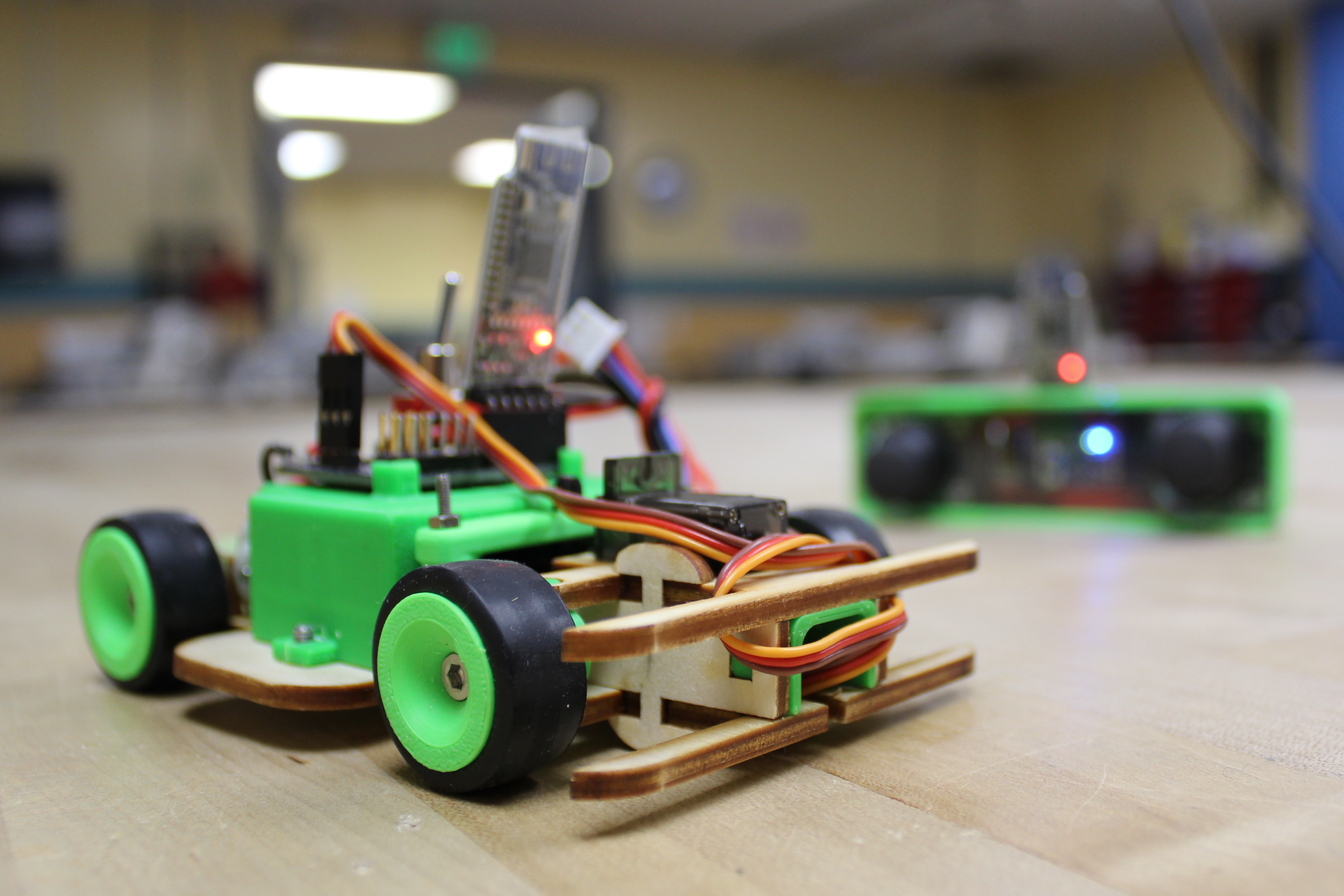
And thats it! Hopefully, you can see endless possibilities using the bluetooth HM-10 to make your next wireless project!
You are now equipped to make some awesome applications using the bluetooth HM-10 module! Rest assure, most bluetooth modules, and even other wireless devices, are often similar. Some have an AT command set. Although we did not cover it here, the HM-10 module can even connect to your phone in a mobile application (coming soon here!). Internet of Things (IoT) technology is massive and growing rapidly, and bluetooth and Wi-Fi are the basis for how most of the IoT technology works. We encourage you to make wireless and IoT projects. A project that we could not resist but make is a wireless bluetooth remove controlled car (BT RC Car). We also have more projects below!