Ditch the breadboard and start making printed circuit boards!
Designed by:
Colin "MrSwirlyEyes" Keef
Have you ever broken open an old electronics device - say, a remote, mouse or keyboard, old phone, even a TV? Surely, you have opened up a desktop computer enclosure to reveal the dusty internals of a computer and seen a printed circuit board. These printed circuit boards were populated with tons of components with traces scribbled all over the board. If you have ever done any prototyping with a breadboard and jumper wires, you have surely felt the pain of the loose jumper wires not staying, debugging where the jumper wire that just came out belongs, and perhaps even a short circuit. Regardless, breadboard prototyping is essential in the learning process. But if you are ready to take the next step in prototyping, then ditching the breadboard is essential and making printed circuit boards is this next step!
Printed circuit boards, or PCBs, are the best way to create reliable prototypes that do not rely on jumper wires (for the most part). However, there are more benefits than just not having to use breadboards and jumper wires. PCBs are much quieter, that is - less noisy! A concept that may have not affected you in day-to-day making... yet. This becomes essential when you have motors that are pulling lots of current and sensitive analog signals on the same board. PCBs are the superior means to taking any custom prototype to market.
Futhermore, PCB design is a highly employable skill. Autodesk offers an affordable way to create PCBs right off the bat with EAGLE. The industry standard, Altium Designer, is relatively expensive but offers an immense array of powerful tools. KiCAD is a completely open source PCB design software and another great option to consider to learn PCB design. The reason we stick with EAGLE here is that it is arguably the most commonly used software for PCB design that is supported by the community from giants such as Sparkfun and Adafruit. The concepts of PCB design can carry from software to software, the only change is the interface and the tools at your disposal. So regardless, starting today with EAGLE can be your next step to designing your very own printed circuit board!
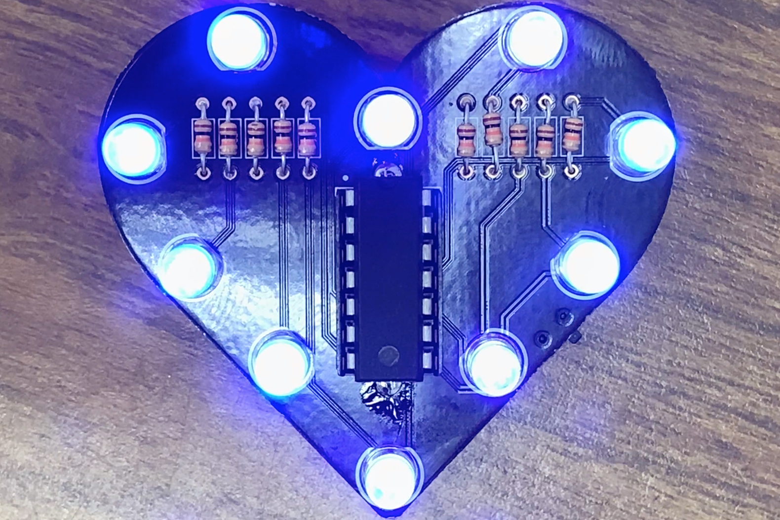
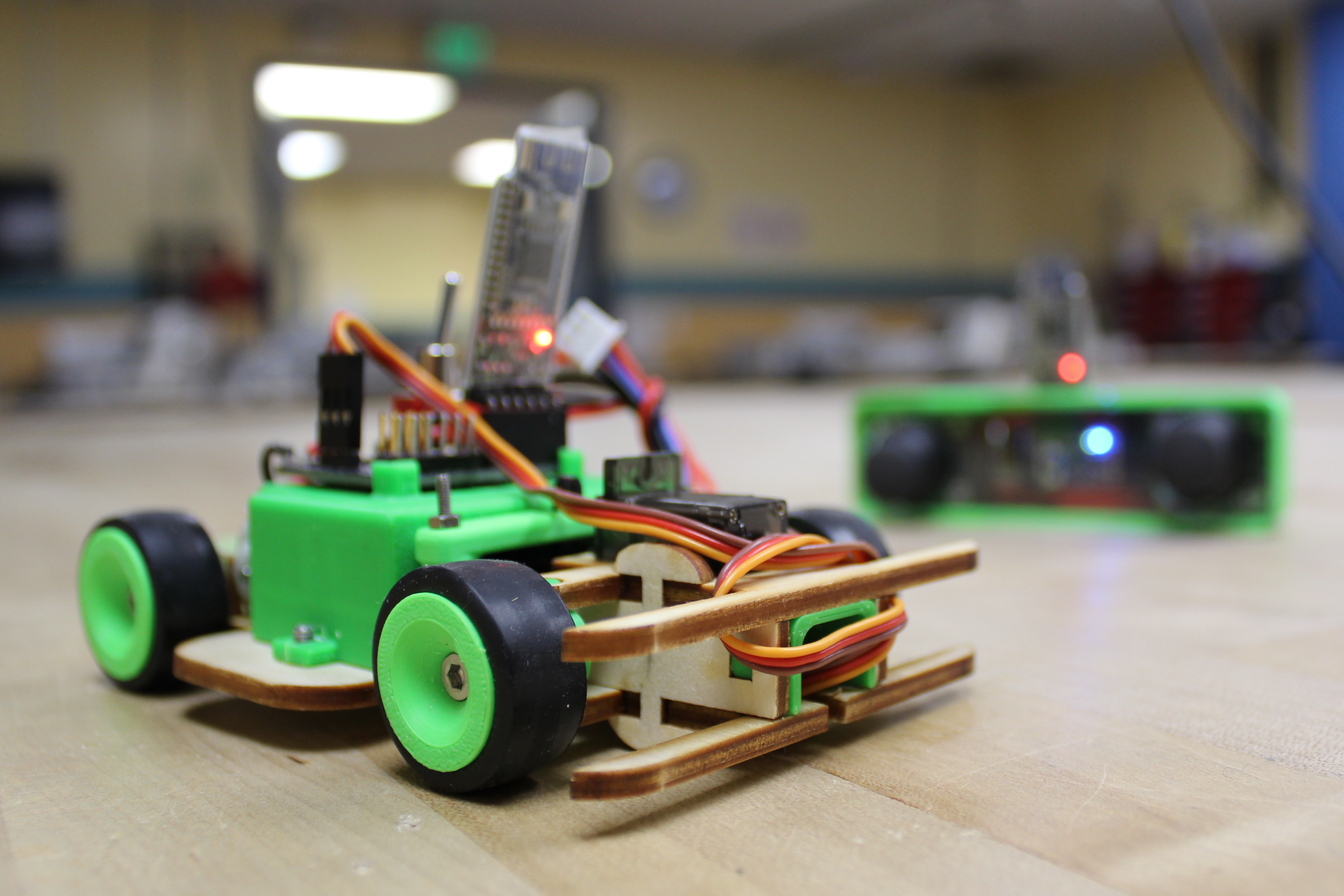
In this module, we are here to motivate you of EAGLE's capabilities with several projects that we have designed. From simple rectangular-shaped boards to unique shapes, a 2D interface to a 3D model of your PCB board, EAGLE is a powerful tool. Combined with Fusion360 (or exporting a STEP file into SolidWorks - our personal perference), you can make your mechatronics solution a reality.
Next, we get you started downloading and installing EAGLE, introduce you to the interface, and get you configured to start making. We equip you with an optional, but highly recommended, 3rd party library - that is, our very own Project in a Box EAGLE libraries which equips you with a large arsenel of popular devices and the ability to generate a bill of materials instantly.
First, we want to get you psyched to get started with EAGLE to show you a narrow range of EAGLE's capabilities - including the 3D model PCB boards that are possible with Autodesk Fusion360.
Typical download and installation instructions, opening EAGLE for your very first time, and introducing the Control Panel!
A brief introduction to the Schematic and Board interface - much more to come very soon! We dive straight into the EAGLE settings and configurations so you can get comfortable with your PCB design software.
Then, we encourage you to download and integrate our Project in a Box EAGLE libraries to have access to hundreds of tested components with a built-in bill of materials in the EAGLE metadata so ordering the components for your board is easy!
At this point you are fully equipped to start making PCBs with EAGLE, so let us start making fun!
In this module, we introduce you to the EAGLE schematic editor. When working with EAGLE, as well as other PCB design software, you are working on a snappable grid. It makes working easy and neat. Schematics are generally rigid and right-angled in terms of connections made. The schematic is just the logical layout, or representation, of your schematic. It is not until we get into the board layout editor where you can let your creativity and artistic imagination run wild.
Another unique - and quite personally our favorite feature of EAGLE - is the built-in CLI (command line interface) or text commands. If you are like us and loathe using the mouse, and believe hot-keys and keyboard usage is the fastest and most efficient method of working with any piece of software - then you will surely come to love EAGLE! EAGLE's built in command lines means that, unlike traditional hot-keys, you can type your commands into the (nearly always) active CLI to change tools (e.g. move, copy, delete, change, via, group, etc.). Now, you should be skeptical - technically a hot-key is faster than typing - and we agree. But EAGLE's text commands allow you to customize the tool at the same time (e.g. change layer top, route 10mil, rotate R45, etc.). Using a traditional hot-key is faster, but if you want to change settings about the tool in traditional programs, you usually still require clicking - but with EAGLE, you can combine the setting configurations for the tool in the same text command. This means you can even make your own macros and scripts to perform multiple commands in succession - however, we do not cover this feature in the introduction, so stay tuned for more advanced tuortials)! EAGLE's text commands are weird to get used to at first, but it is a powerful tool.
We will show you how to add parts and how to properly connect them together using the net tool. Just as with any schematic drawing, we introduce power symbols to create nodes (e.g. GND, VCC, 5V, 3.3V, etc.) that connects your power buses together, and cleans up your schematics.
Starting off with an introduction to the EAGLE schematic interface. How to reveal and configure the grid. Introduce text commands through the EAGLE CLI (command line interface)
Demonstrating how to get started adding parts to your schematic and how to connect your component schematic symbols together to make a complete circuit. We introduce the first taste of the power of the Project in a Box EAGLE libraries and how the metadata helps you learn about your components with easy access to datasheets, and connecting you with a distributor to buy your components without the pain of searching around. In addition, we briefly comment on the different kinds of component and their packaging standards.
We are done creating our PCB schematic and the schematic interface has served its role as being the abstraction in the PCB design process. Next, we explore the tangible and practical aspects of PCB design - the board layout!
In this module, we explore the art of engineering with the EAGLE board layout. This is arguably where the real PCB designing begins, this is what you will print, and this is where you can be creative.
We introduce the very basics - which unfortunately means very boring. We will show you how to shape your board for the very simple rectangle-shape. Stay tuned for a tutorial to import more creative and exciting board shapes! And, we highlight the parallel between the schematic and board interface, including their similarities and differences.
Finally, we complete the design of our board, placing our components from the schematic, and routing them together to make the electrical connections that will be printed. We introduce polygons and show you how to create power/ground planes.
Introduction to the EAGLE board layout interface. Again, we revisit the grid, except now in the board layout. We highlight how to reshape your board into a simple rectangle (for more advanced and creative board shapes, stay tuned for our future tutorials), and placing components onto your PCB board.
We introduce the EAGLE DRC (design rule check) as a tool to make sure your board is within the manufacturer's tolerance, and to check for (manufacturing) errors on your board layout design. Here we feature OSH Park as our board house and how to integrate their design rules into the EAGLE environment so that you are confident that the board you design meets the manufacturability of OSH Park's 2-layer board service.
Finally, we do the work of routing our board to make the electrical connections that will be realized during the manufacturing process. We introduce polygons which are largely used to create power/ground planes for your PCB board. Power planes are an extremely powerful concept in PCB design, most notably in the realm of noise. We only briefly cover them by introducing how to make them, stay tuned for advanced tutorials and even some of our projects that explore and employ the potential of power planes.
At this point, we are essentially done designing our first PCB board! However, there is still more to learn and utilize by creating 3D models of our PCB board with Fusion360 and actually manufacturing our board.
We bring the introduction to EAGLE tutorial to a close by flexing the combined power of the Autodesk suite with the tightly coupled EAGLE and Fusion360 programs. We have been working with EAGLE using a 2D interface, however we can sync our 2D design with Autodesk Fusion360 to realize our PCB board in 3D! This 3D model can then be used freely in Fusion360 to integrate your PCB into your mechanical design. You can even export your 3D model into a STEP file to be used in other 3D modeling software such as SolidWorks - we will introduce this in a future tutorial!
Disclaimer: As of this writing, Autodesk Fusion360 is only offered as a free trial.
As of this writing, Autodesk has not enabled the sharing of libraries, so you may not be able to generate the 3D models as shown in this tutorial.
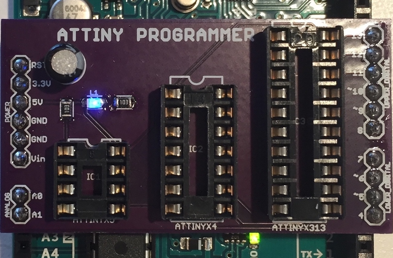
We, again, feature OSH Park as an easy-to-use service to get your very PCB design manufactured in a beautiful purple finish! We also introduce how OSH Park's board preview generator is a great way of verifying your design and as a realization of what your board ought to look like in its finish.
As described, we show you how to generate a 3D models of your PCB using Fusion360 and how to order your PCB board through OSH Park!
As of this writing, Autodesk has not enabled the sharing of libraries, so you may not be able to generate the 3D models as shown here.
If you made it this far, you have completed the introduction to EAGLE tutorial. However, we include a bonus module to show how you can generate a BoM (bill of materials) for your PCB board so that, in addition to ordering your PCB board, you can order the necessary components for your PCB!
Throughout the tutorial, we kept floating this idea of EAGLE metadata and is the reason why we would like to encourage you to use our PiB EAGLE Libraries. That is, we put a ton of effort into making a library that contained information about each device we put into our PCB board. Why? So that we can utilize EAGLE's built-in ULP (user language program) that will generate a BoM (bill of materials) in a form that is easily imported into a spreadsheet program (e.g. Microsoft Excel, Google Spreadsheets, Numbers, etc.).
This can make organizing and ordering your PCB components worlds easier and save your hours if your design contains hundreds of components! We feature the electronics distributor Digikey as our primary supplier our electronics.
Quick lesson to show how to run EAGLE's BoM ULP and import the CSV (comma separated values) into Microsoft Excel. The process should be similar for any other spreadsheet program.
And that is it for our introduction to EAGLE! There is still a ton to learn, and the best way to learn is to get lost in the software - so get to it Nerd!
We have barely graced the surface in our introduction to EAGLE or PCB design. There are several powerful tools and features in EAGLE yet to be explored that will enable and empower you to build more complex designs - and build them faster! The same can be said for PCB design in general in the realm of signal integrity, heat dissipation, and design practices both general and for specialized cases (e.g. radio frequency circuits).
However, hopefully we have got you over the initial barrier so that you may start exploring EAGLE and PCB design for yourself now. This opens many doors for you. If you have never soldered before, then learning how to solder will be paramount to putting your PCB board together. This will include through-hole soldering and surface mount soldering (e.g. reflow soldering)!
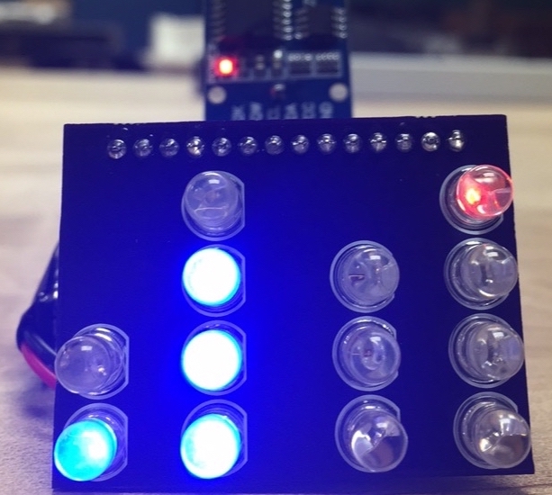
You can now make your own custom circuits or even products that you can push to market. Create your own Arduino UNO or customized project that you can call your own. We have several tutorials and projects to get you started with learning how to program microcontrollers and even make your own custom designs using EAGLE!
Of course, stay tuned for more intermediate and advanced EAGLE PCB Design tutorials in the near future so that you can delve deeper into the art of PCB design and explore the potential of Autodesk EAGLE!