This tutorial has the basics to get you familiar with Arduino. It is geared to prepare you for all our Arduino based projects. It is not necessary for you to do every module in this tutorial on your first pass. You may need to come back to recall information for other tutorials or projects.
Several of our modules will use the Arduino UNO, but any Arduino variant (and even some non-Arduino boards) will work with small variations to code.
Unfortunately, this tutorial is not focused on teaching you the basics of programming in general. The Arduino programming language is based on Wiring. However, if you are familiar with the C/C++ programming language, you will quickly realize that syntactically the code you type in the Arduino IDE is largely C/C++. And we under the hood, there is a library that is automatically included that allows us to use the (very familiar) Arduino functions that will read and write from the Arduino development board pins. We will get into this in more detail, however just keep in mind that we will gloss over some of introduction to programming and good programming practice. Finally, we we believe the best way to learn how to use the Arduino IDE and Arduino development boards is through working examples to expose you to the material and self-exploration. So always experiement for yourself as you are learning - and we promise by doing so you will learn more!
Furthermore, we will not go over the details of the electrial knowledge in there of. We assume the reader is familiar with reading circuit schematics and understands the fundamentals of electronic circuits. It is nothing to worry about, however, as we will not being doing anything complex that requires extensive circuit knowledge.
Naturally, this tutorial is always a work-in-progress, so check back frequently!
| DEVICE | VENDOR URL | QUANTITY | NOTES |
|---|---|---|---|
| Arduino UNO R3 | Digikey | 2 | May use other variants, but may need minor changes to code. |
| USB Cable (A Male to B Male) | Digikey | 2 | |
| LED BLUE CLEAR T-1 3/4 T/H | Digikey | 13 | Can substitute for any desired color LED. |
| RES 10K OHM 1/4W 5% AXIAL | Digikey | 13 | Can substitute for appropriate sized resistor(s). |
| Breadboard (small) | Digikey | 2 | Used for prototyping. |
| Jumper Wire M/M 6 (20pcs) | Digikey | 2 | Used for prototyping. |
In this module, we install the Arduino IDE so you can get started programming hardware using Arduino.
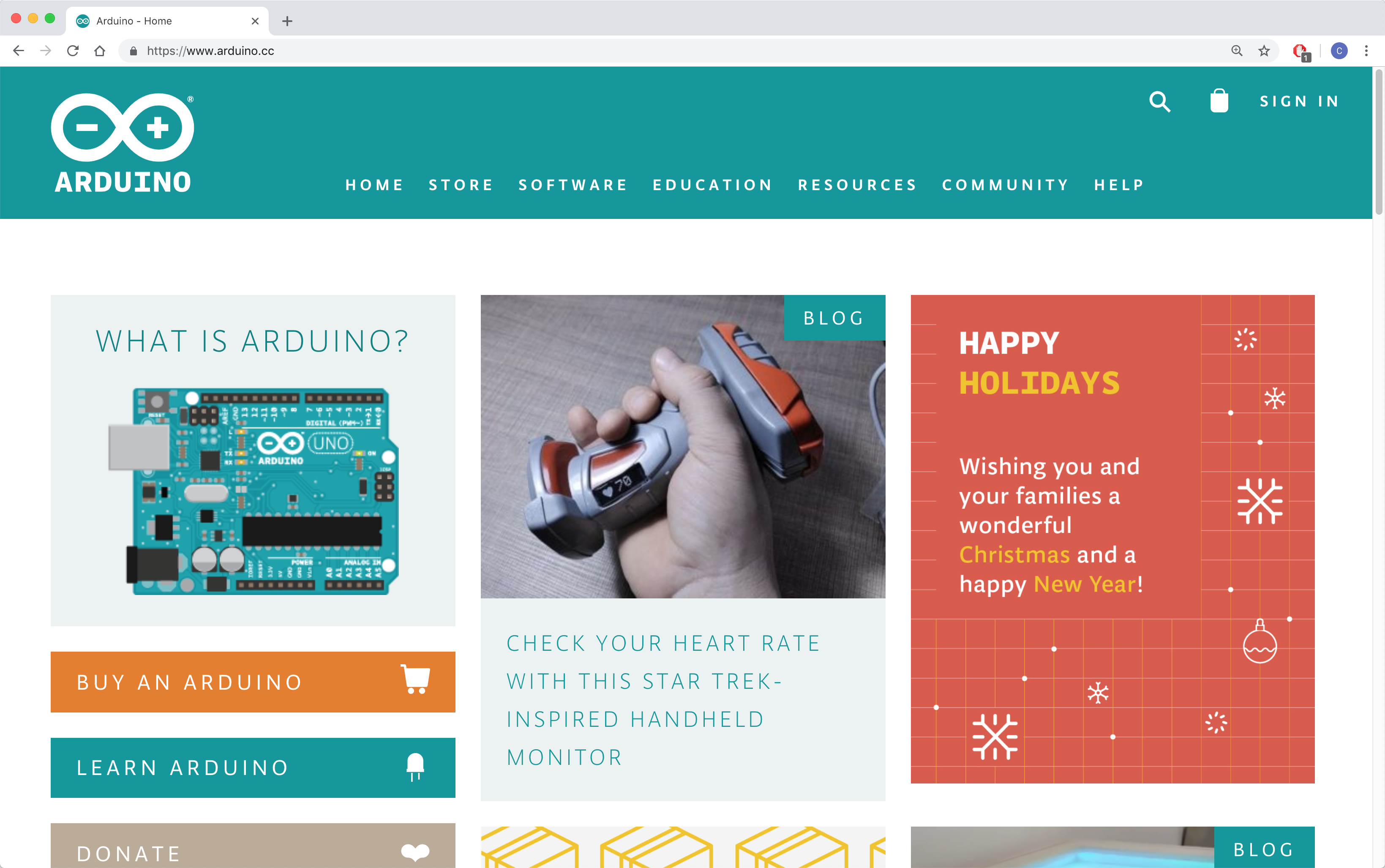
Visit the Arduino homepage: https://www.arduino.cc/.
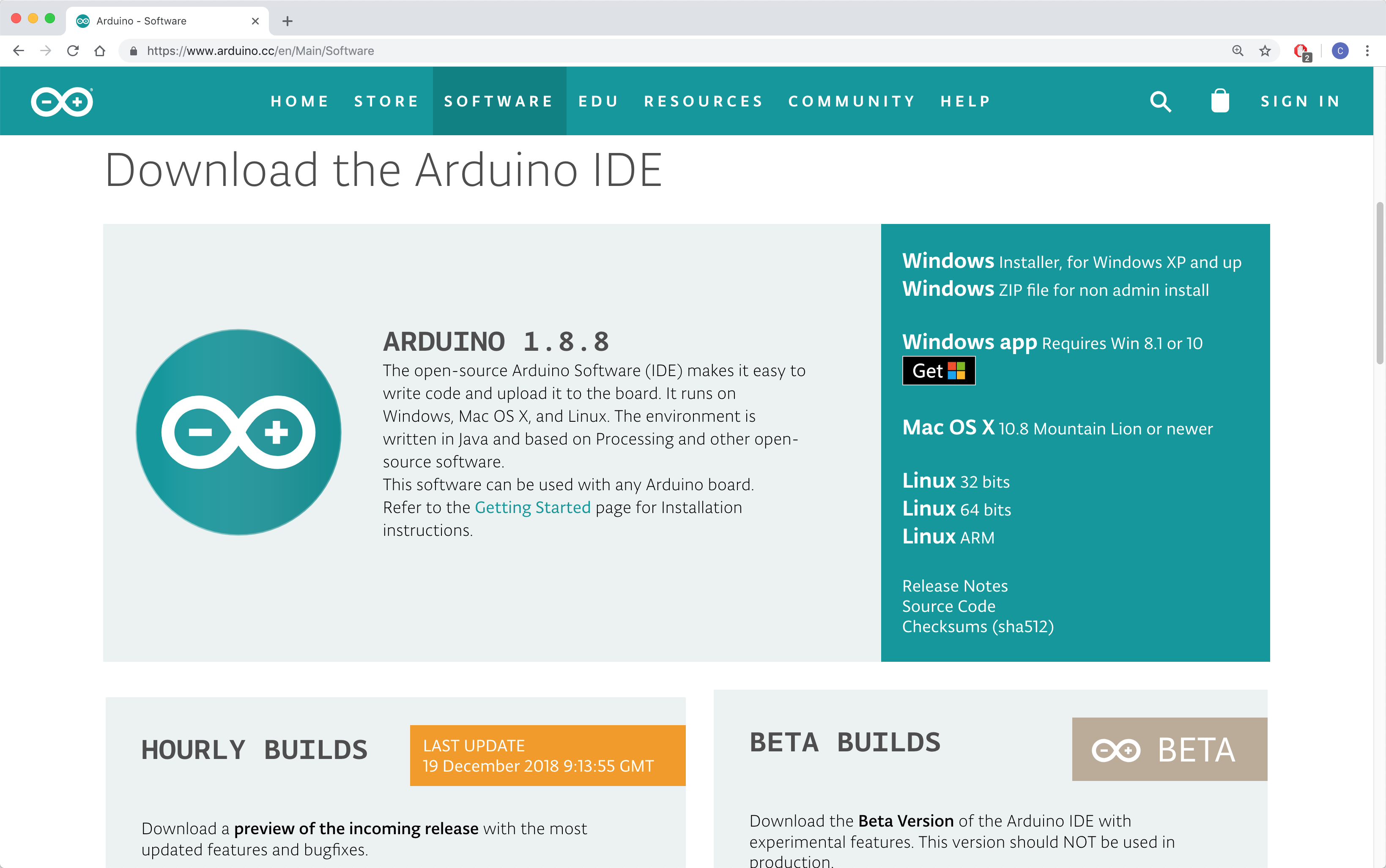
Navigate to SOFTWARE > DOWNLOADS.
Scroll down a bit to see the download options. Arduino is supported for Windows, Mac OS X, and Linux platforms. Select the appropriate platform for your system.
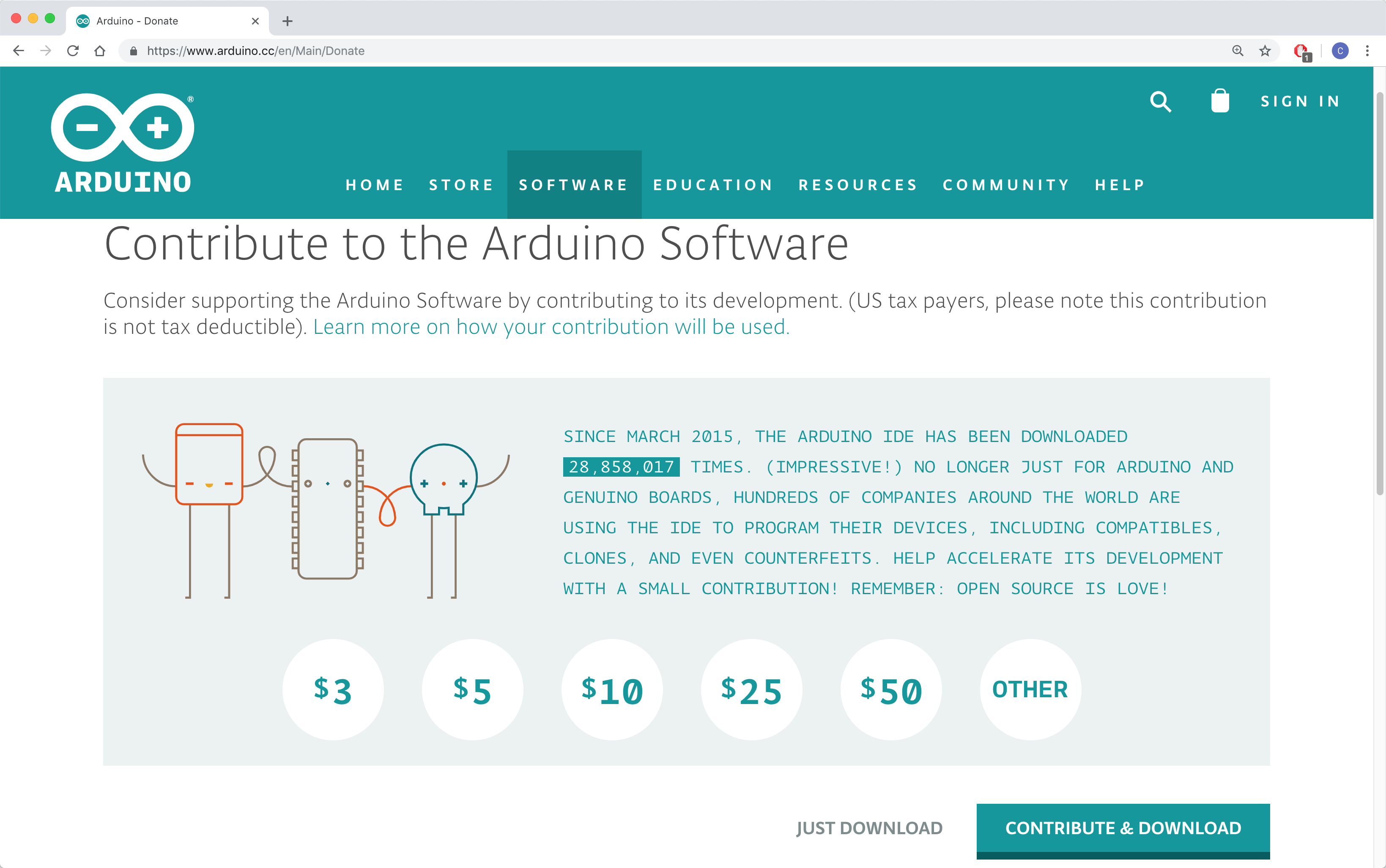
Next, you will be taken to a page where you are encouraged to contribute a donation to Arduino. Select your desired option.
Depending on which OS you selected for your download and installation, follow the appropriate path:
TODO
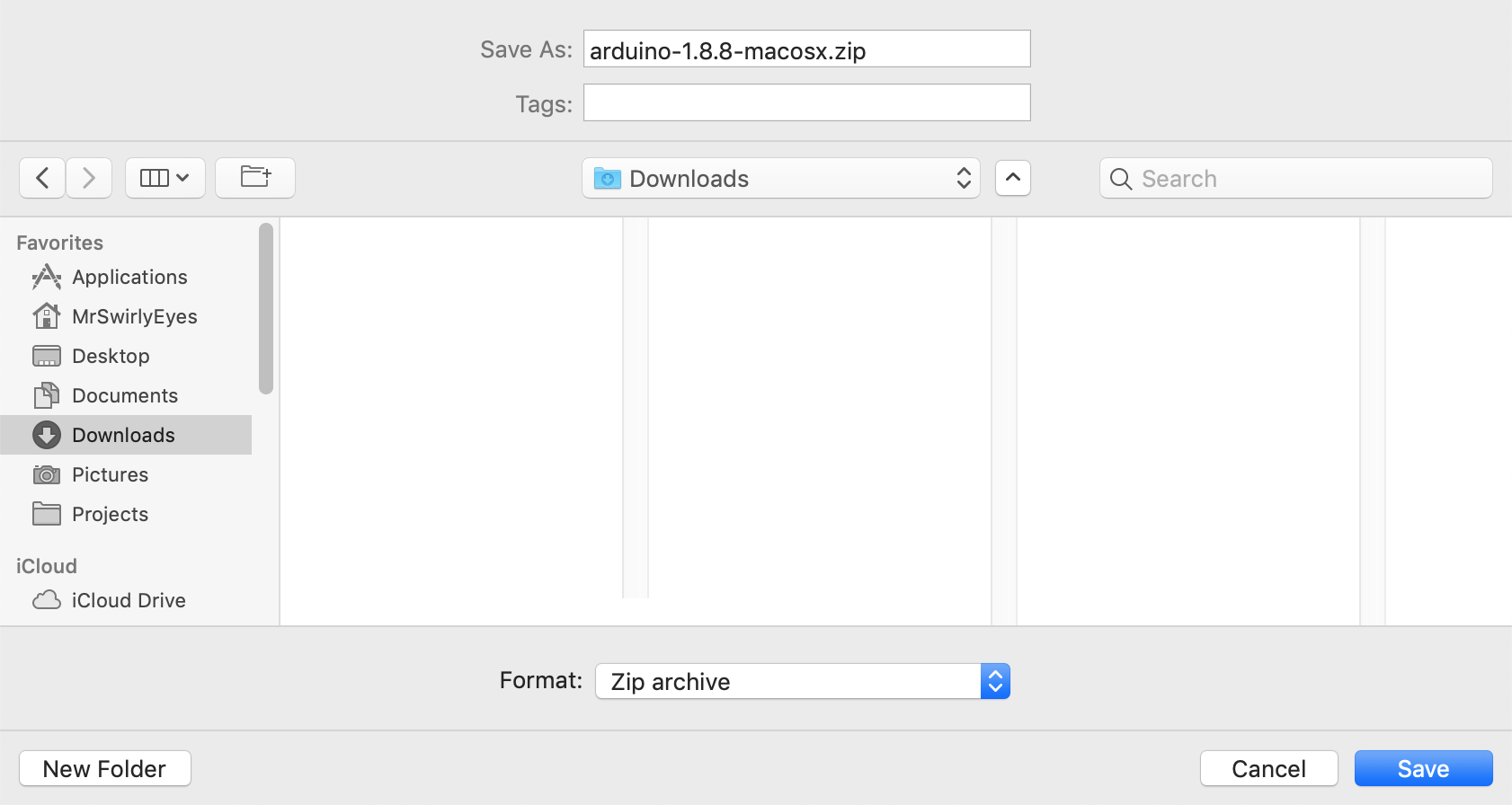
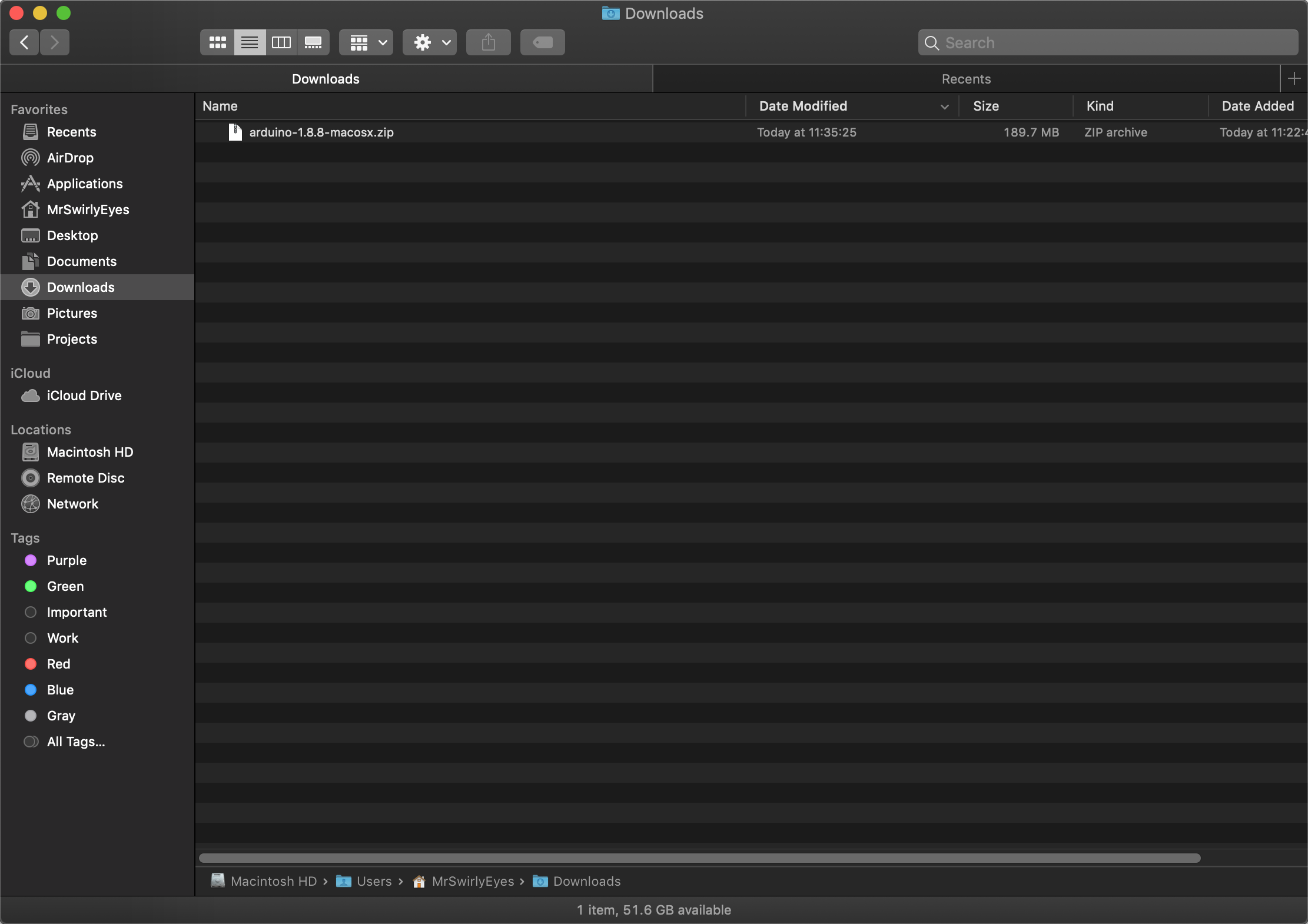
After you complete your contribute option, the Arduino IDE download should initiate automatically. Download the .zip anywhere (e.g. Downloads).
Navigate on your system to the folder where you downloaded the Arduino IDE .zip. Double-click on the .zip to unzip the Arduino application.
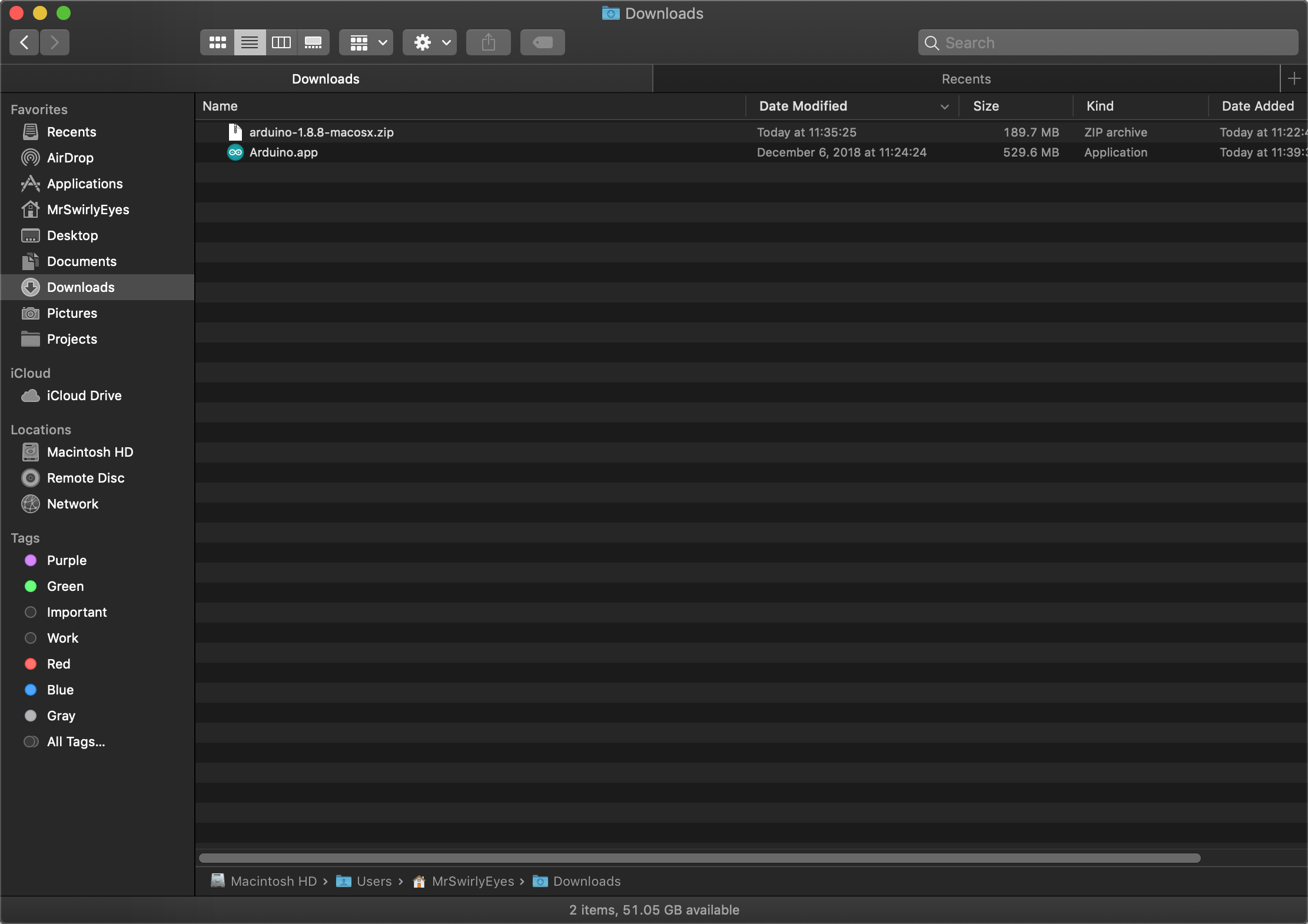
The unzipping process should only take a few seconds.
After which, the Arduino IDE application becomes available in the same directory. Next, drap the Arduino application into your Applications folder.
After which, you can use the Mac Spotlight search to launch Arduino, or navigate to your Applications folder, and double-click on the Arduino application.
The first time you launch the Arduino application, Apple double-checks if you trust opening this application. Click Open.
The Arduino IDE will load the necessary packages.
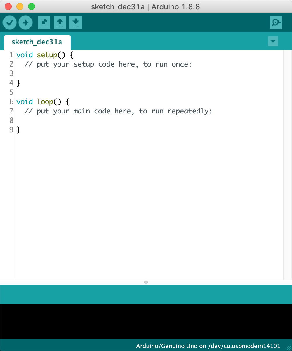
Then the Arduino IDE will open.
That is it, you are ready to start using the Arduino IDE for your projects!
todo
Now you should have the Arduino IDE installed and ready to go!
In this module, we will introduce you to the Arduino IDE and everything you need to know to get started. We will even show you some tips and tricks we think are extremely useful to know now that you will wish you knew if you had missed it.
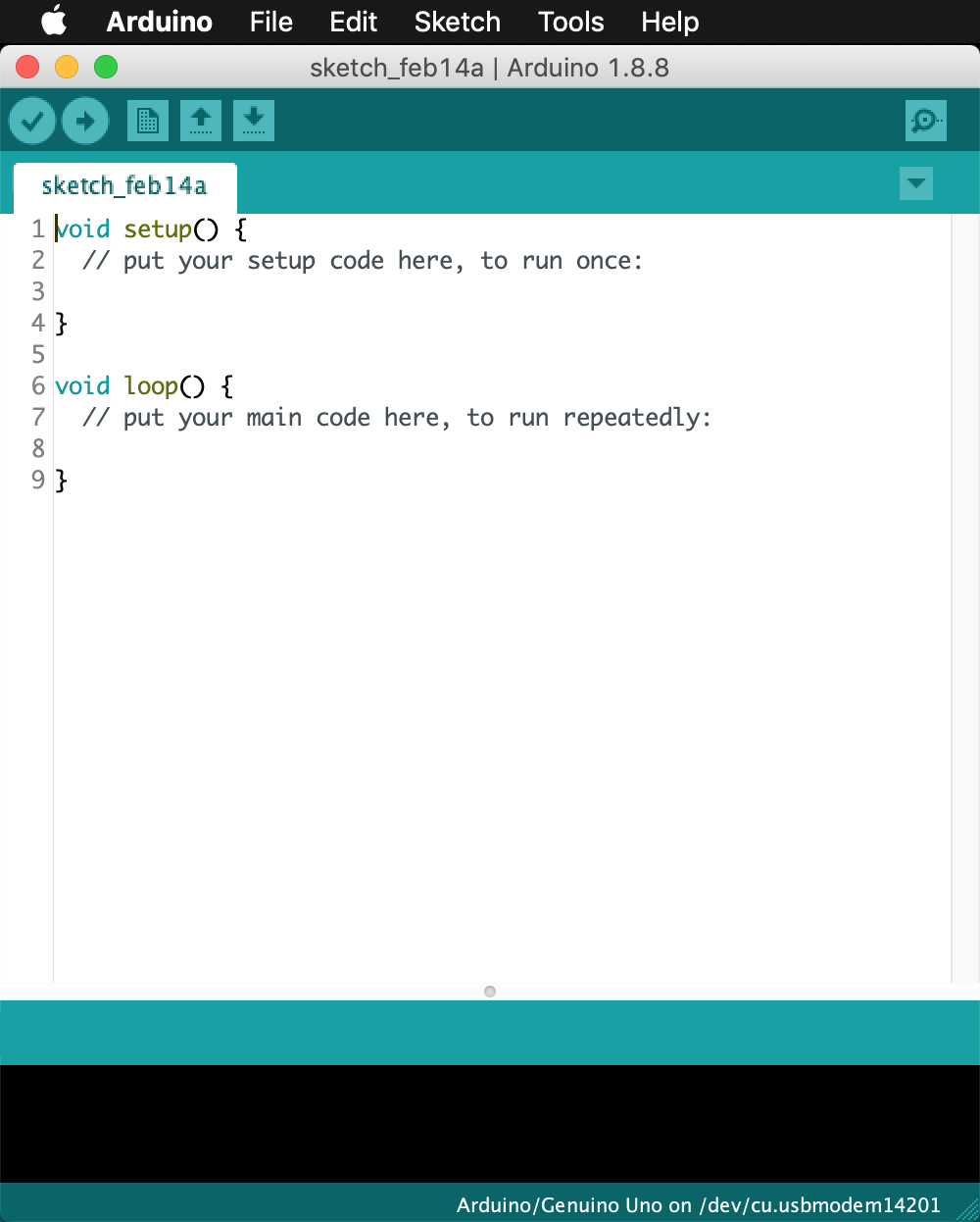
Let us start by first launching the Arduino IDE. It will bring up the program that will look similar to the following:
Breaking down the Arduino IDE down a bit at the top of the window, will show a typical menu that most applications have. If you are using Windows or Linux distributions of the Arduino IDE, they come integrated into the Arduino IDE window. On a Mac (as shown), it does not come attached to the window.
To go through all of the options here would be a bit intense and boring (for you to read, and us to type out). So we will cover these menu options as we use them and as needed, but encourage you to explore what is contained in these menus as well.
A bit further down in the Arduino IDE, the following buttons outline the Arduino IDE toolbar:
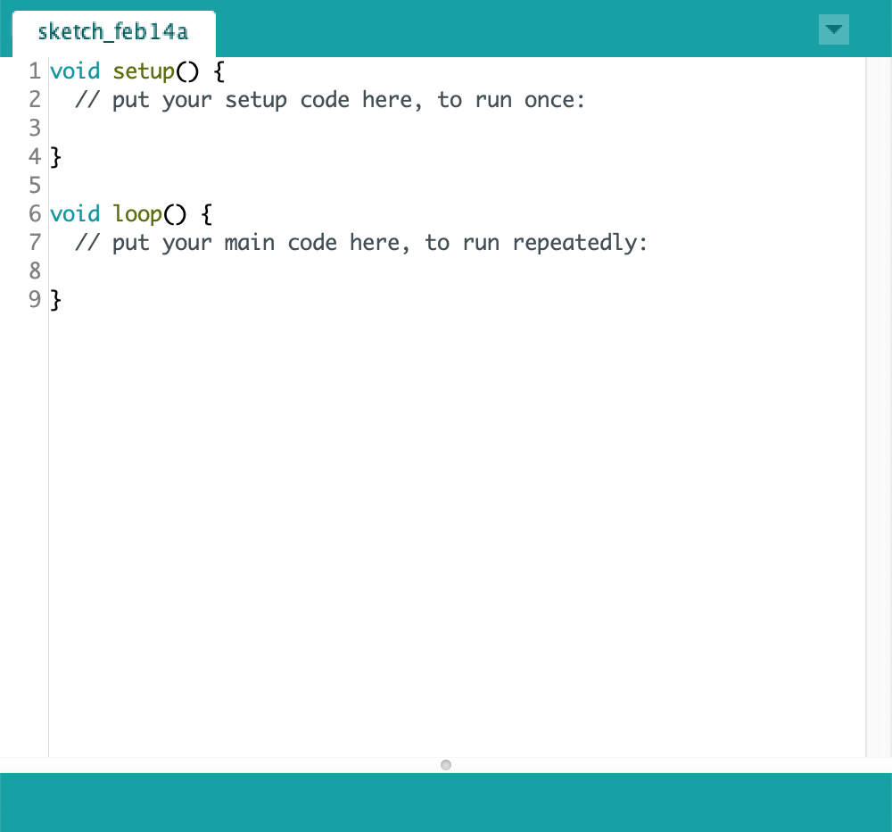
Below the Arduino IDE toolbar is where you is where most of your attention will be. Your Arduino sketch will be present. One window is currently open, with room for future tabs to appear when created.
At the top of the sketch area are the Arduino IDE sketch tabs.
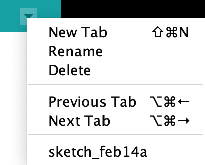
At the far-right of the Arduino IDE sketch tabs is a carat that opens the Arduino IDE sketch tabs menu. Clicking on the carat reveals the following drop-down menu:
The Arduino IDE sketch tabs menu lists the following:
Further down the Arduino IDE we get to the last section the Arduino IDE console output area:
In the black area it will show detailed information about your compile and upload status and any error messages. In the light-green area above that it will generally give you a light-description of the status of the compilation or upload.
In the dark-green area at the bottom of the Arduino IDE simply shows what board and port you currently have selected.
That is pretty much the Arduino IDE broken down at face value. We will now explore some of the most commonly used items in the Arduino IDE.
In this section, we will look at the Arduino IDE Preferences and make recommendations for your preferences that we believe enchance the Arduino IDE experience.
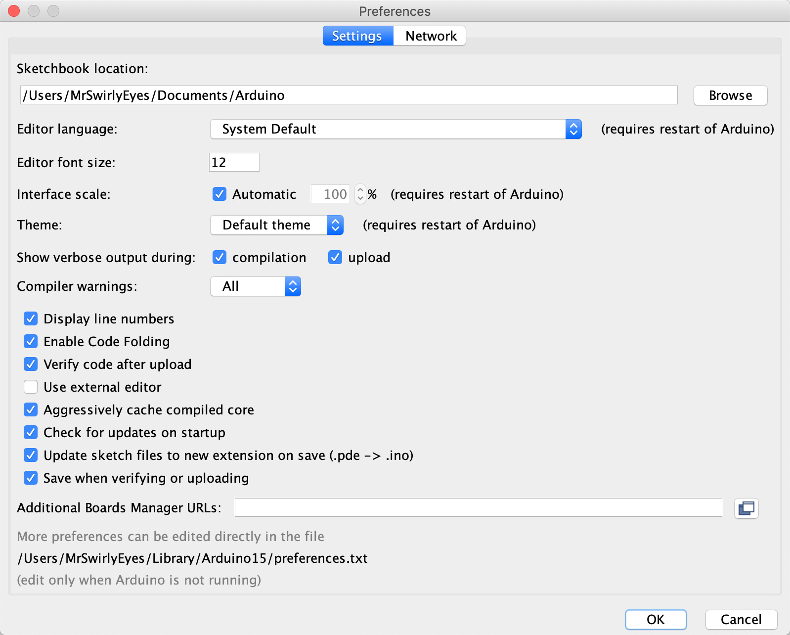
To access the Arduino IDE Prferences, navigate Arduino > Preferences (or CTRL/CMD + ,). If you are using Windows or Linux, navigate File > Preferences.
By default, the Arduino IDE Preferences are as follows:
There are several preferences to choose from, and we recommend the following preferences configuration:
This following is enabled:
There are several other preferences that we encourage you to experiment with. The Additional Boards Manager URLs is useful and we will address this in a later module.
This concludes the introduction to the Arduino IDE and its interface. Next, we get to know the Arduino UNO from a hardware perspective.
In this module, we will examine the Arduino UNO and its hardware. It is essential we understand the Arduino UNO to some degree in order to know what we are doing when programming the Arduino UNO.
We will start off easy with a simple example of toggling an LED ON and OFF.
Now let us get started with some code!
In order to better understand the Arduino UNO configured as an ISP (In-System Programmer), we're going to explore the Arduino UNO in more detail than you may have before. Remember, at the heart of the Arduino UNO is the ATMEGA328p - an AVR microcontroller.
The Arduino UNO development board has the ATMEGA328p as its microcontroller. The family of ATMEGA boards are related to ATtiny boards - both have 'AT-' in the name, which denotes ATMEL (now Microchip), the company that designed and manufacture these micrcontrollers. The ATMEGA microcontrollers are generally more powerful than the ATtiny microcontrollers, but the way we interface with and program them are identical.
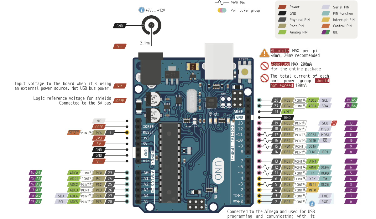
The following diagram illustrates the Arduino UNO R3 pinout for reference:
This image may be overwhelming as it details a lot about the Arduino UNO that is not necessary for most casual makers. However, it shows information that is important for programming AVR microcontrollers. Let's investigate some of these more powerful features as well as some basic features of the Arduino UNO development board.
The Arduino UNO development board conveniently groups and labels these pin (or header) rails:
analogRead function in the Arduino IDE.The '~' denotes a PWM capable pin
In this module, we will introduce the your first Arduino sketch, the Hello World of hardware - blinking an LED!
Although this may seem trivial, or even boring, it is the best first step when working with a new piece of hardware (e.g. Arduino UNO development board, or any other microcontroller) to test out the bare minimum. We like to say, "if you can blink an LED, you can do anything". Although this is far from true, it really is the best place to start and work from there.
This is the first of many modules to come that will introduce the ins and outs of the Arduino IDE and working with Arduino development board variants. Although we will be largely focused on the Arduino UNO, most of the ideas and concepts can be extended to other Arduino development board variants and in some cases to other microcontrollers!
Now, without further adieu, let us make fun!
We will start off easy with a simple example of toggling an LED ON and OFF.
Construct the following circuit to connect the Arduino UNO to a single LED:
Programming the LED is about as simple as the circuit. The following is the typical blink sketch that is commonly used as the "Hello World" of hardware:
To run the code. Be sure to select:
Then click on the Upload button (or press CTRL/CMD + U) to upload the code to the Arduino UNO.
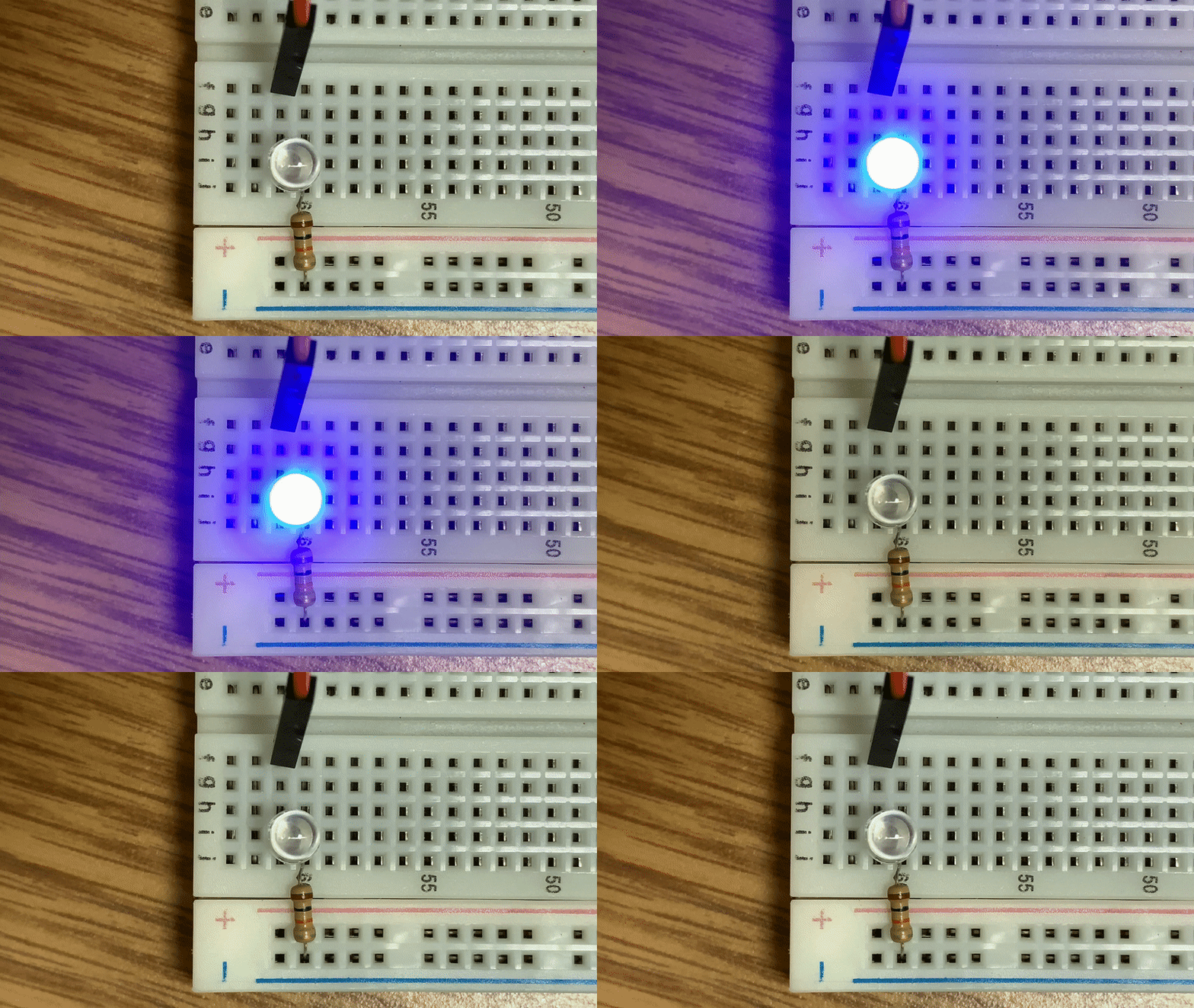
The behavior should be as follows:
An LED toggling ON and OFF every 500ms (0.5s). Easy right? Now lets build atop this!
In this challenge, we want to build an array of leds using the Arduino UNO. This is simply to expand what we have learned in the single LED example and We will have 10 LEDs in our Heart, so we need to expand our single LED example to 10.
Construct a circuit to program 10 LEDs (with the appropriate corresponding resistors) using the Arduino UNO. You may use any valid pins you want. However, we recommend (in general) avoiding pin 0 (RX) and pin 1 (TX).
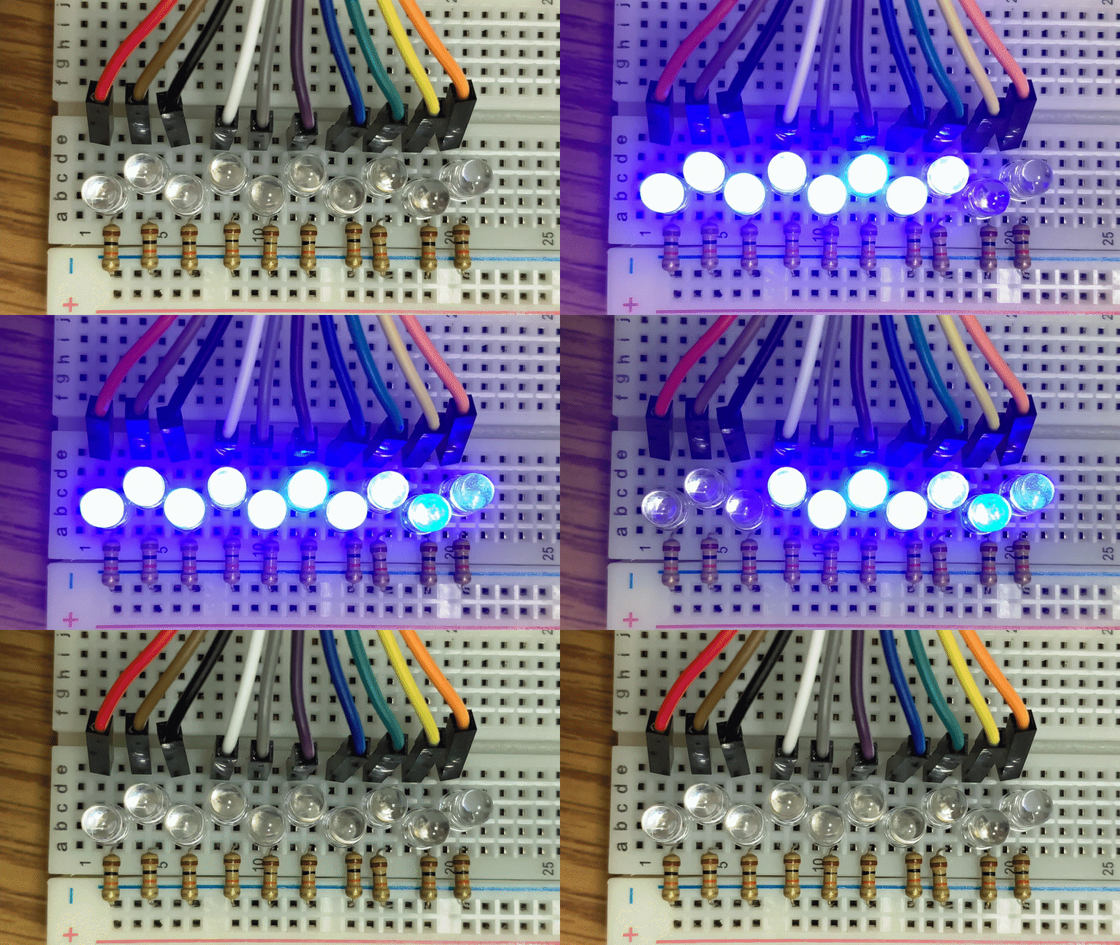
You may program any behavior you want. We will demonstrate the same behavior as the single LED extended to the array of 10 LEDs. Here is an example of our challenge solution:
Any LED behavior is acceptable, as long as all the LEDs demonstrate functionality.
If you are using the Arduino IDE's Serial Monitor, then the LED on pin 0 and 1 may behave wonky when writing to it. Pin 0 (RX) and pin 1 (TX) are shared with the Serial Monitor (e.g. when you use Serial.print(...)) so any device (e.g. LED) may receive a HIGH or LOW signal even if you are explicitly writing a particular value to it (or not).
Note that this solution is NOT the only solution. This is just how we realized it. It should look almost exactly the same as the code we started with when testing the single LED. The only difference is the addition of several more LEDs. We also employed an array for its ease, convenience, and code readibilty.
The schematic should be similar to the following:
Again, the code can vary, but here is what we have for our solution:
Hopefully this challenge was not too difficult, this was meant to be very simple - after all, we just started. The value in this project is to demonstrate the transition from prototyping to product!
In this module, we will install a library into the Arduino IDE so you can use it in any project.
There are many methods of installing libraries. We will go over one of these ways. We will be using a random generic library. However, this process can be done for any Arduino library in the appropriate format.
The library we are installing was borrowed from the Arduino official site. This library may not be the most useful library for any application, but will illustrate how we install a library into the Arduino IDE.
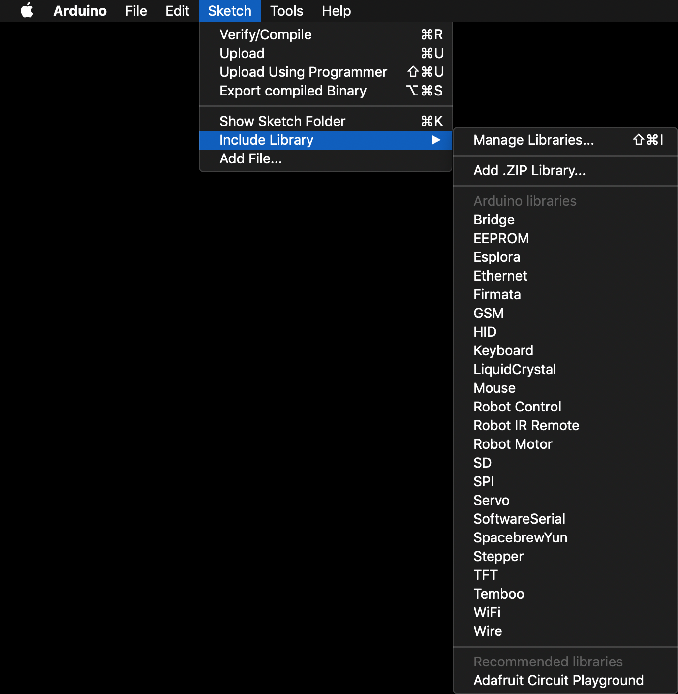
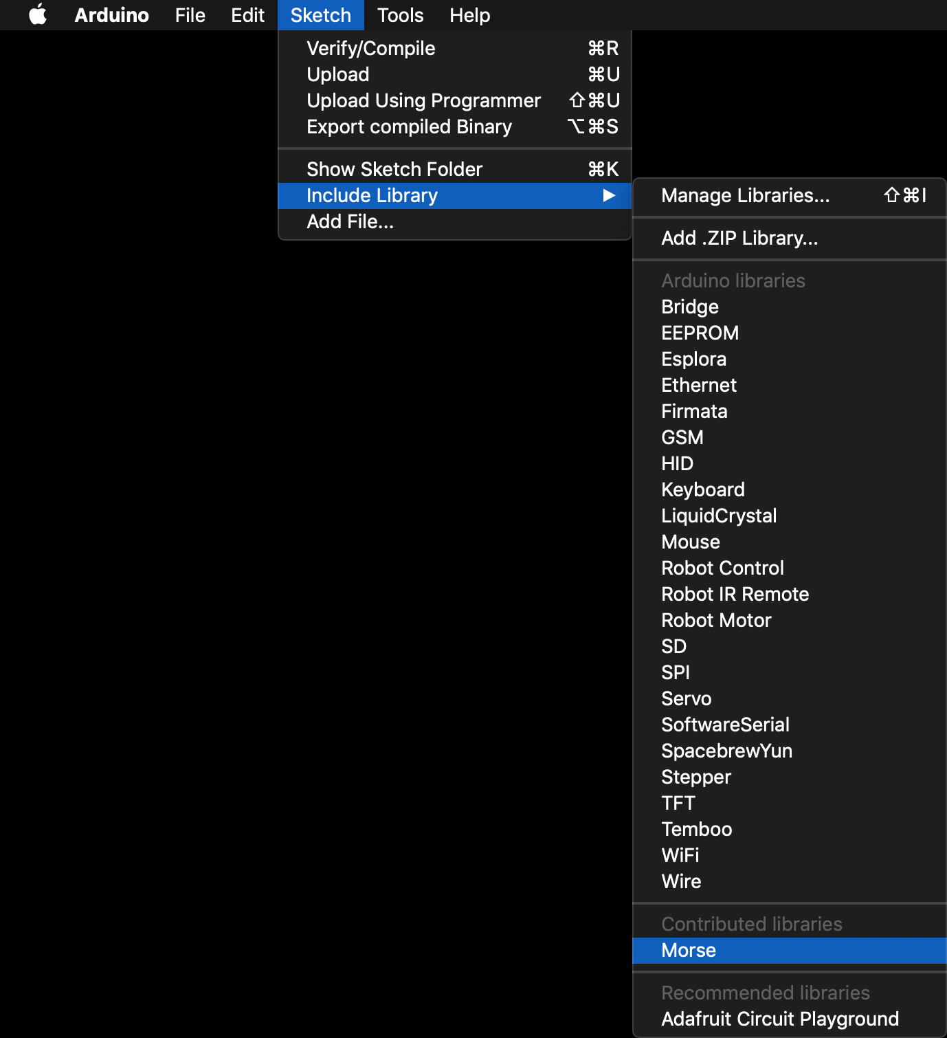
Launch Arduino. Navigate to Sketch > Include Library and observe that Arduino IDE comes with several libraries installed by default.
We are now going to install a library. After which, coming back to that menu will yield our new Contributed Libraries.
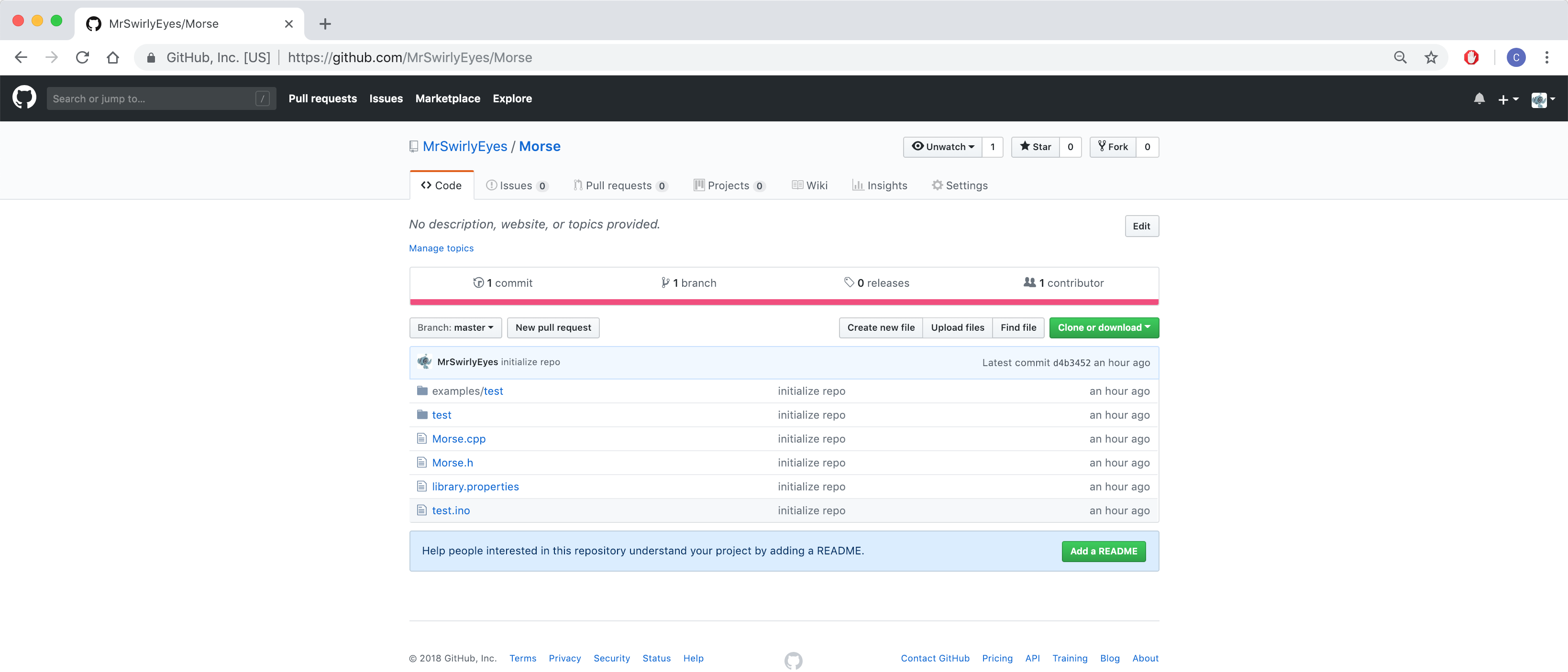
Navigate to the MrSwirlyEyes' Morse GitHub repository.
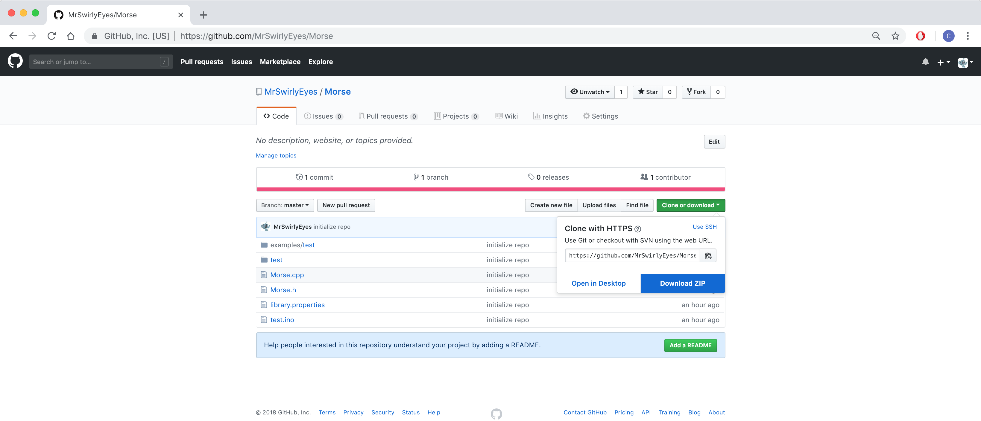
Click on the large green Clone or download button. A small menu appears under it. Click on Download ZIP.
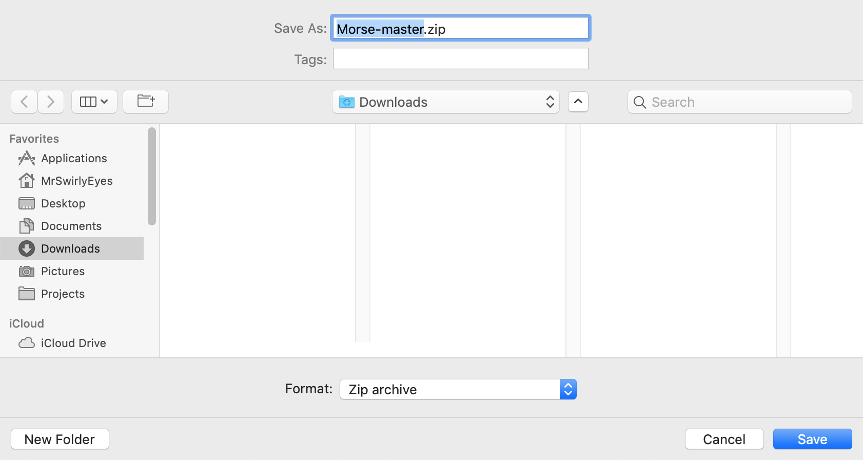
Save the Morse-master.zip somewhere on your system (e.g. Downloads).
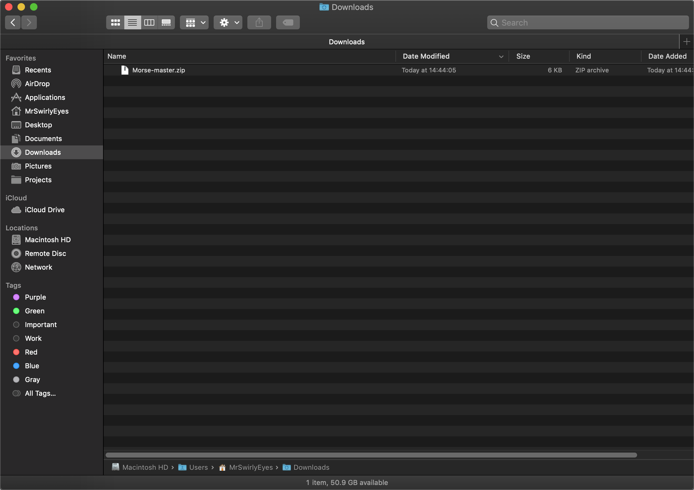
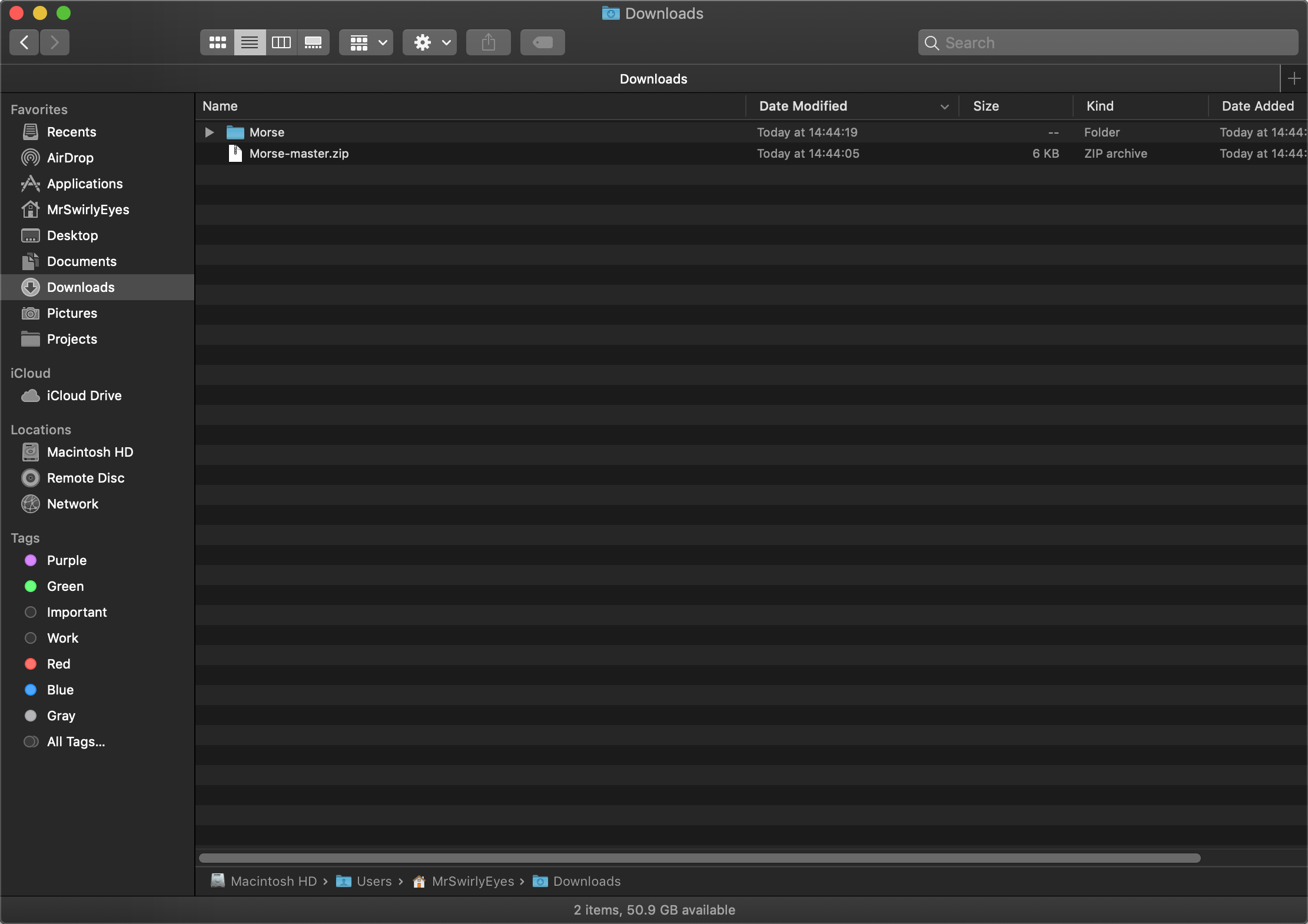
Navigate to the folder where you downloaded the .zip file.
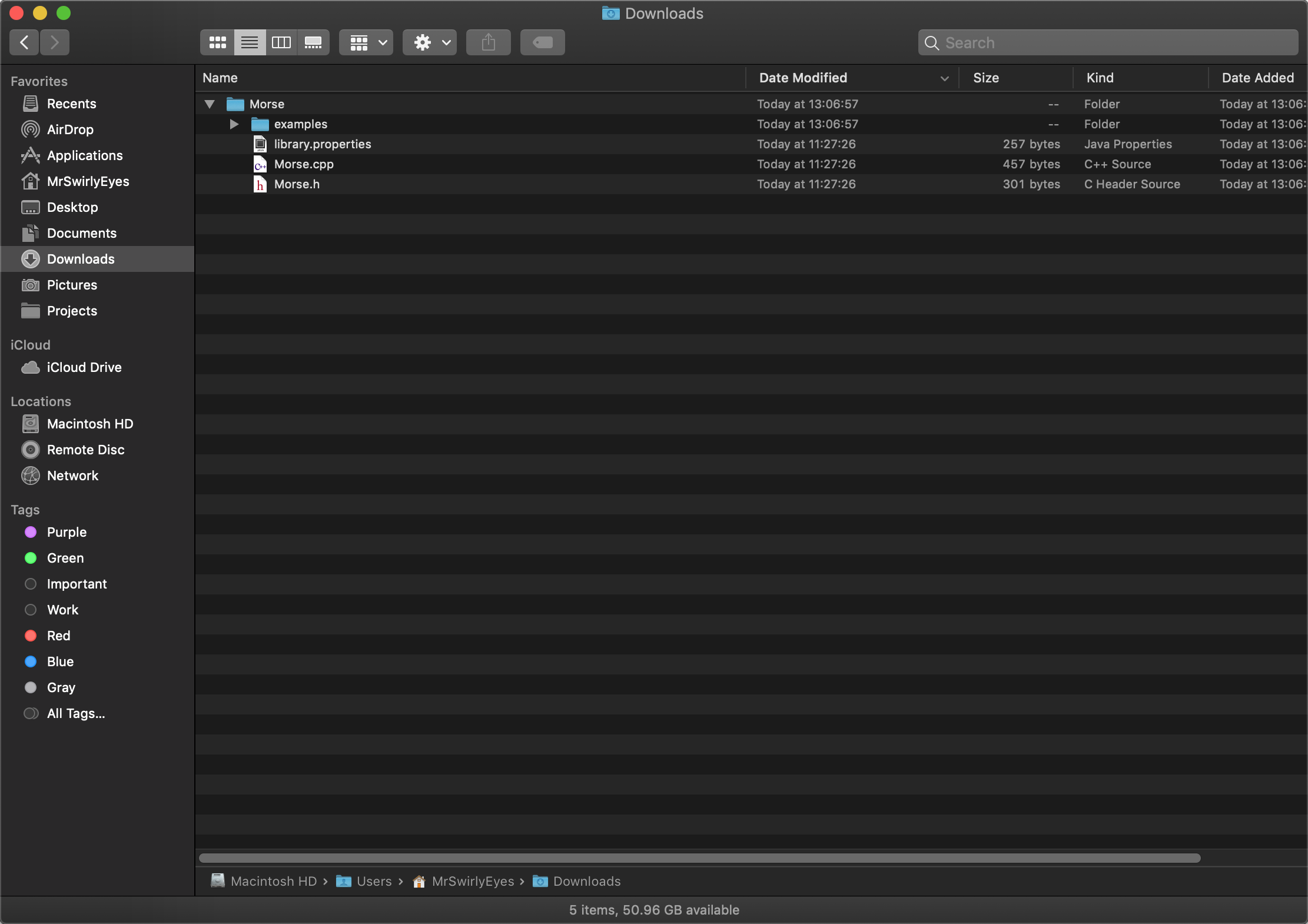
Double-click on Morse-master.zip to unzip the file and reveal the Morse library folder.
Delete the Morse-master.zip.
Feel free to explore the Morse folder and its file contents. The directory structure is in a particular way so that when we install it into the Arduino IDE, it can give us Examples. In this case, we will have one example code called test. The Morse.cpp and Morse.h file are the Morse library contents. The library.properties file contains metadata about the library.
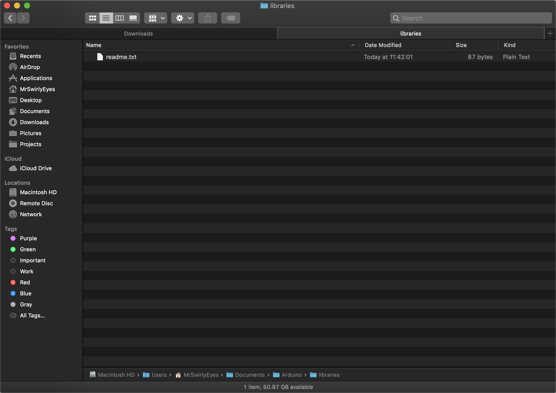
Open a new Finder (or Windows Explorer) window or tab. Navigate to Documents > Arduino > libraries.
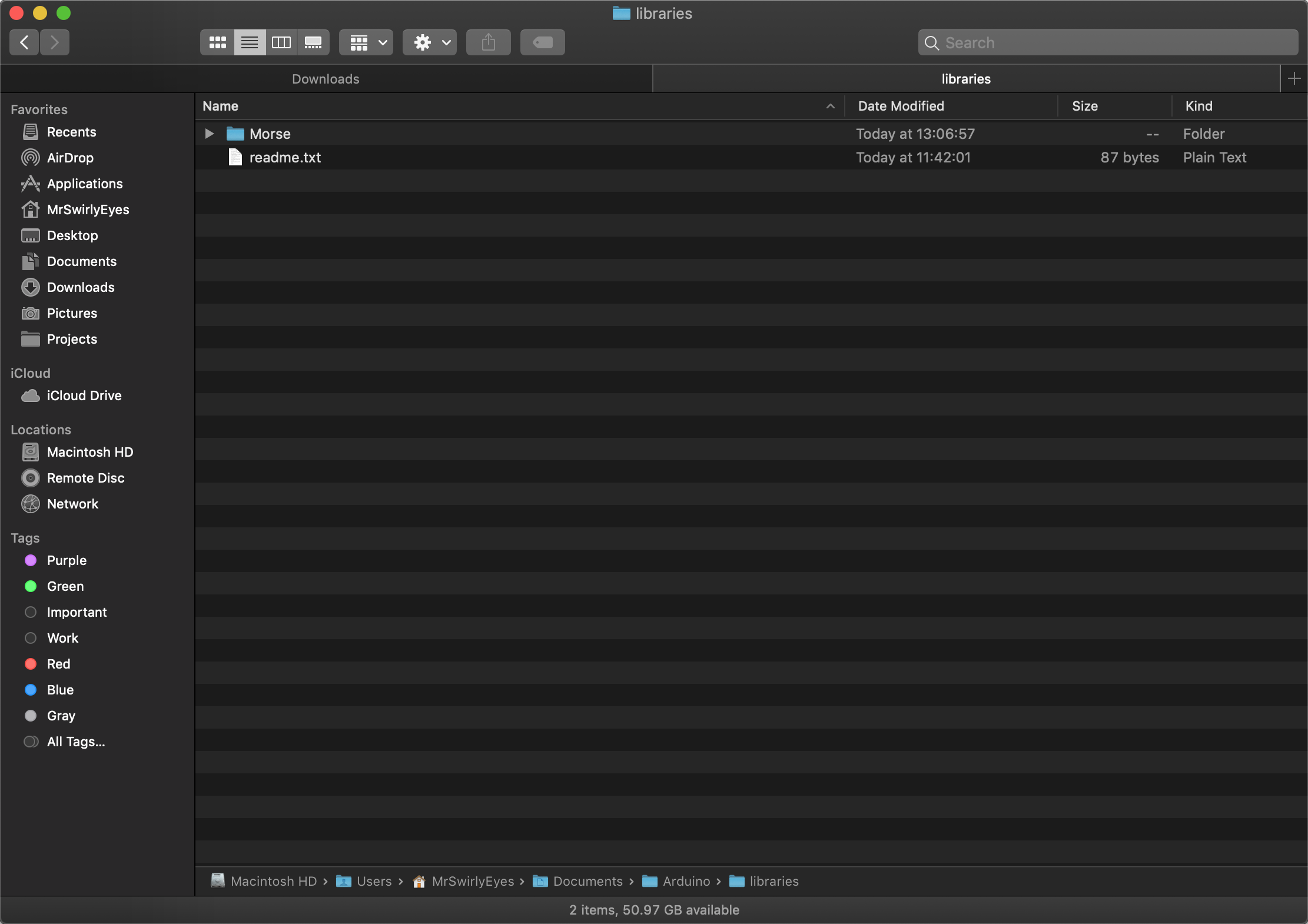
Drag-and-drop the Morse folder into the libraries folder.
Close the Arduino application.
Re-launch the Arduino application. Navigate to Sketch > Include Library and observe we have a new section called Contributed libraries where our Morse library is now installed.
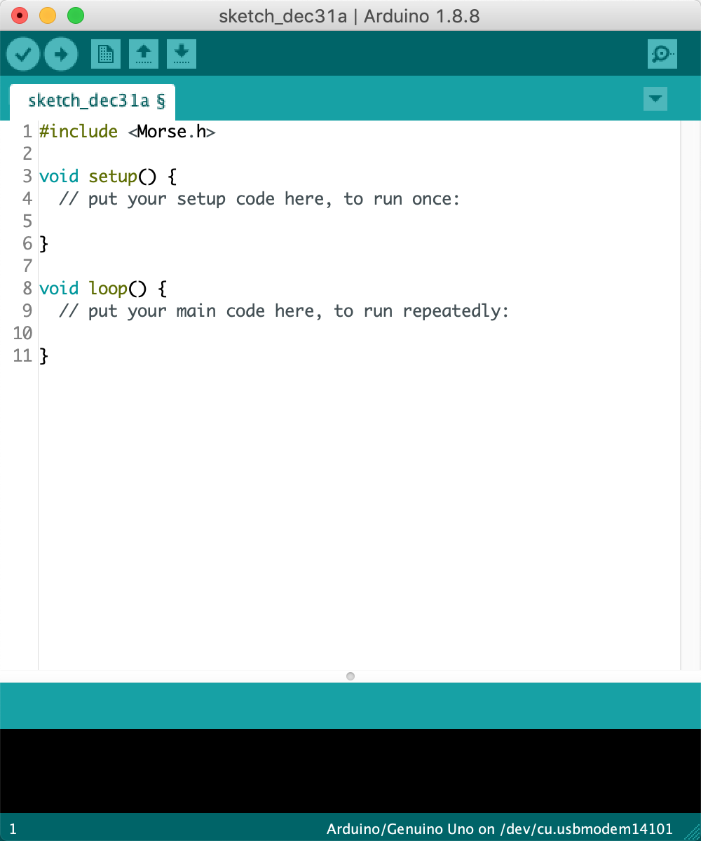
Click on Morse to include it in your current Arduino sketch.
You will now be able to use the Morse library class, functions, etc. Of course, this assumes you know how it works already. You can explore the Morse.cpp and Morse.h in Documents > Arduino > libraries > Morse and learn about how to use the library.
Many libraries also include examples on how to use the library.
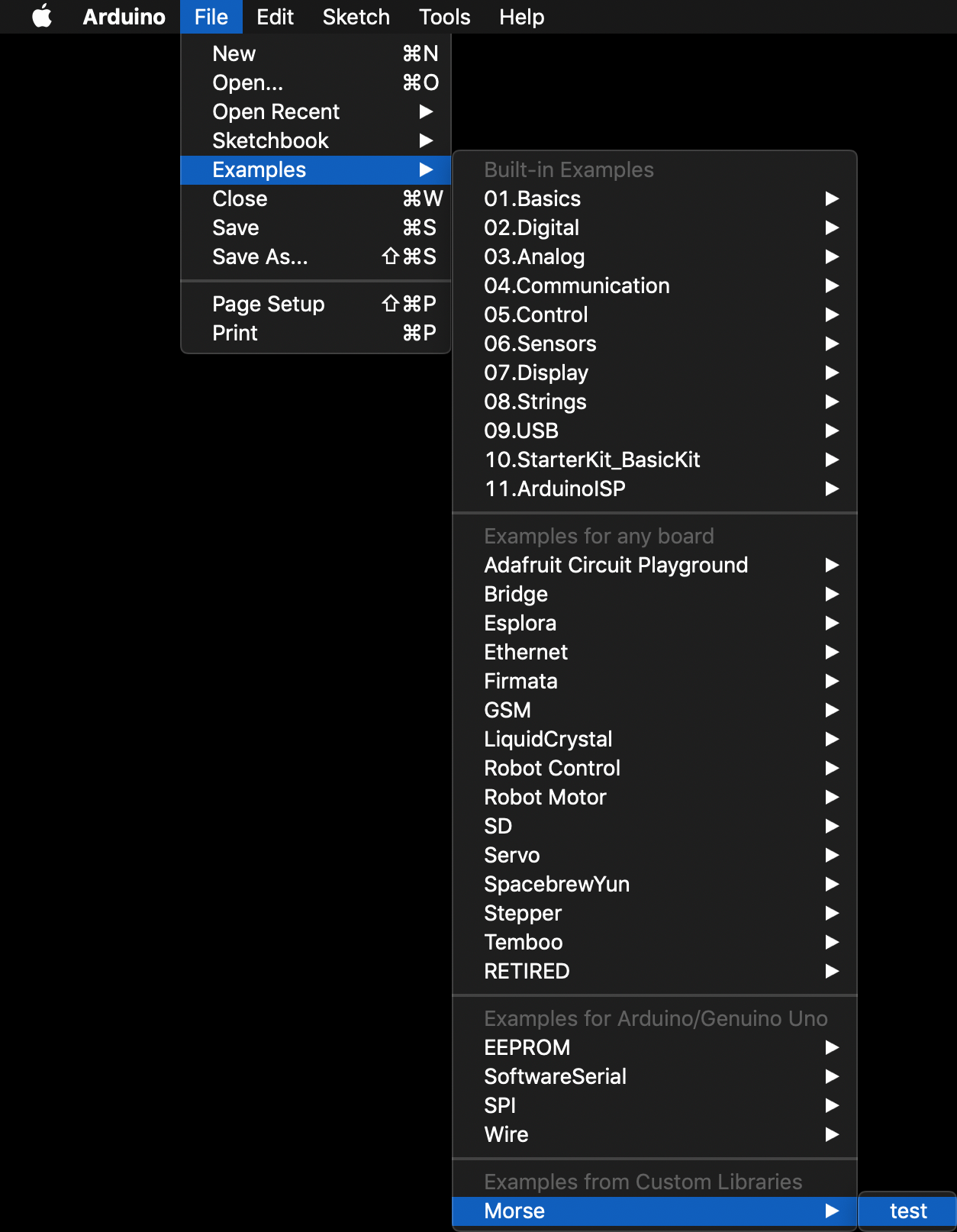
You can check by navigating File > Examples and towards the bottom there is a (new) Examples from Custom Libraries where our Morse library is. If you highlight Morse, you will see all the example libraries. In this case, there is only one and it is called test.
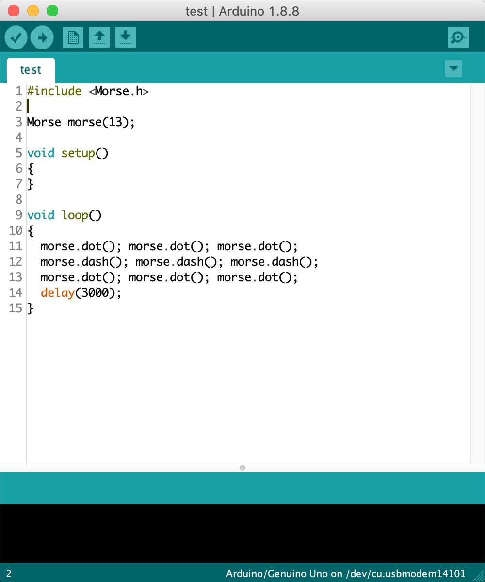
Clicking on the test will open the associated example code.
We encourage you to plug in your Arduino variant and test it out for yourself.
You have now installed a library into the Arduino IDE and it is ready to go. There are thousands of user created libraries out there. Installing them is the same way. You can also create your own libraries too!
In this module, we explore configuring the Arduino UNO's Serial Peripheral Interface (SPI) pins.
todo
A closer look at the pinout diagram reveals many interesting labels for each of the pins. We are going to focus on the ones that are of particular importance for programming AVR microcontrollers. These pins are the Serial Peripheral Interface (SPI). SPI is a synchronized data protocol used by microcontrollers to communicate with one another over short (physical) distances. In an SPI connection, there is always one Master (e.g. Arduino UNO) that will control (or program in our case) peripheral devices, namely, the target AVR microcontroller.
The SPI pins are named and labeled as follows:
Find these pins on the Arduino UNO pinout diagram below and be aware of their location on your Arduino UNO and other AVR microcontrollers. In the same diagram, we highlight the In Circuit Serial Programmer (ICSP) header. This header appears in many AVR microcontroller development boards. It is a standardized interface for bootloading and programming AVR microcontrollers.
Observe that the ICSP Pinout header and digital pins 10-13 are connected together!
The AVR Pocket Programmer uses ths ICSP header! We will be using an Arduino UNO here without the standard header, but functionally we are doing the same thing without the extra hardware purchase.
The SPI is what we will use to program the AVR microcontrollers when we configure the Arduino UNO as an In-System Programmer ISP). This makes the Arduino UNO a little bit more powerful. The ability to program other AVR microcontrollers using an AVR microcontroller...whoa...deep. Let us now proceed to configuring the Arduino as an ISP.
In this module, we explore configuring the Arduino UNO's Inter-Integrated (I2C) Pins.
todo
A closer look at the pinout diagram reveals many interesting labels for each of the pins. We are going to focus on the ones that are of particular importance for programming AVR microcontrollers. These pins are the Serial Peripheral Interface (SPI). SPI is a synchronized data protocol used by microcontrollers to communicate with one another over short (physical) distances. In an SPI connection, there is always one Master (e.g. Arduino UNO) that will control (or program in our case) peripheral devices, namely, the target AVR microcontroller.
The SPI pins are named and labeled as follows:
Find these pins on the Arduino UNO pinout diagram below and be aware of their location on your Arduino UNO and other AVR microcontrollers. In the same diagram, we highlight the In Circuit Serial Programmer (ICSP) header. This header appears in many AVR microcontroller development boards. It is a standardized interface for bootloading and programming AVR microcontrollers.
Observe that the ICSP Pinout header and digital pins 10-13 are connected together!
The AVR Pocket Programmer uses ths ICSP header! We will be using an Arduino UNO here without the standard header, but functionally we are doing the same thing without the extra hardware purchase.
The SPI is what we will use to program the AVR microcontrollers when we configure the Arduino UNO as an In-System Programmer ISP). This makes the Arduino UNO a little bit more powerful. The ability to program other AVR microcontrollers using an AVR microcontroller...whoa...deep. Let us now proceed to configuring the Arduino as an ISP.
In this module, we explore configuring the Arduino UNO as an In-System Programmer. This is useful in the event that you are bootloading and/or programming an AVR microcontroller. That is, you could program an Arduino UNO with an Arduino UNO - yes, this is possible! Or program ATtiny microcontrollers with an Arduino UNO. See our AVR microcontrollers tutorial if you are interested!
Configuring the Arduino UNO as an ISP (In-System Programmer) is extremely easy. Arduino already supports this feature and has their own Example Sketch for programming the Arduino UNO to be an ISP.
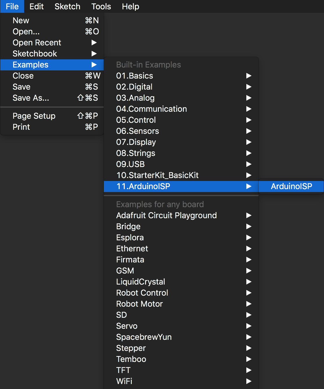
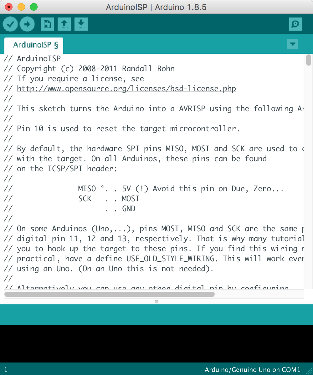
Launch the Arduino UNO IDE. Navigate through File > Examples > 11.ArduinoISP and select the ArduinoISP sketch.
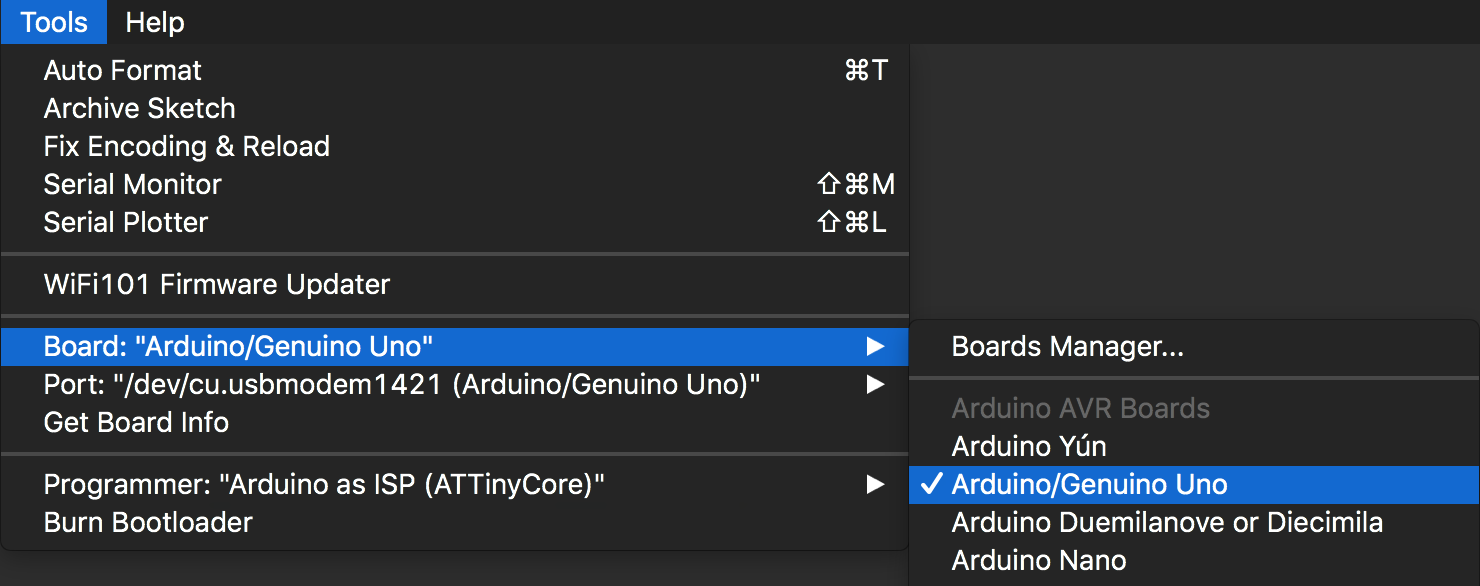
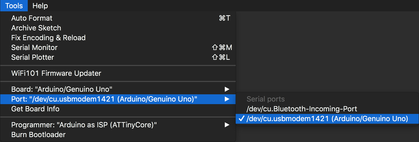
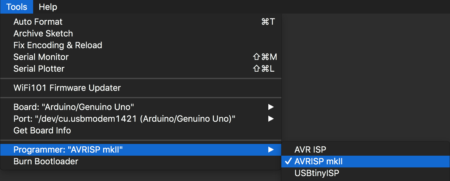
Before we program the Arduino UNO with the ArduinoISP sketch, we need to set the following settings in the Tools menu:
Port names are variable across different operating systems (Windows, Mac OS, and Linux) and physical USB ports.
Finally, you can upload the ArduinoISP sketch to the Arduino UNO.
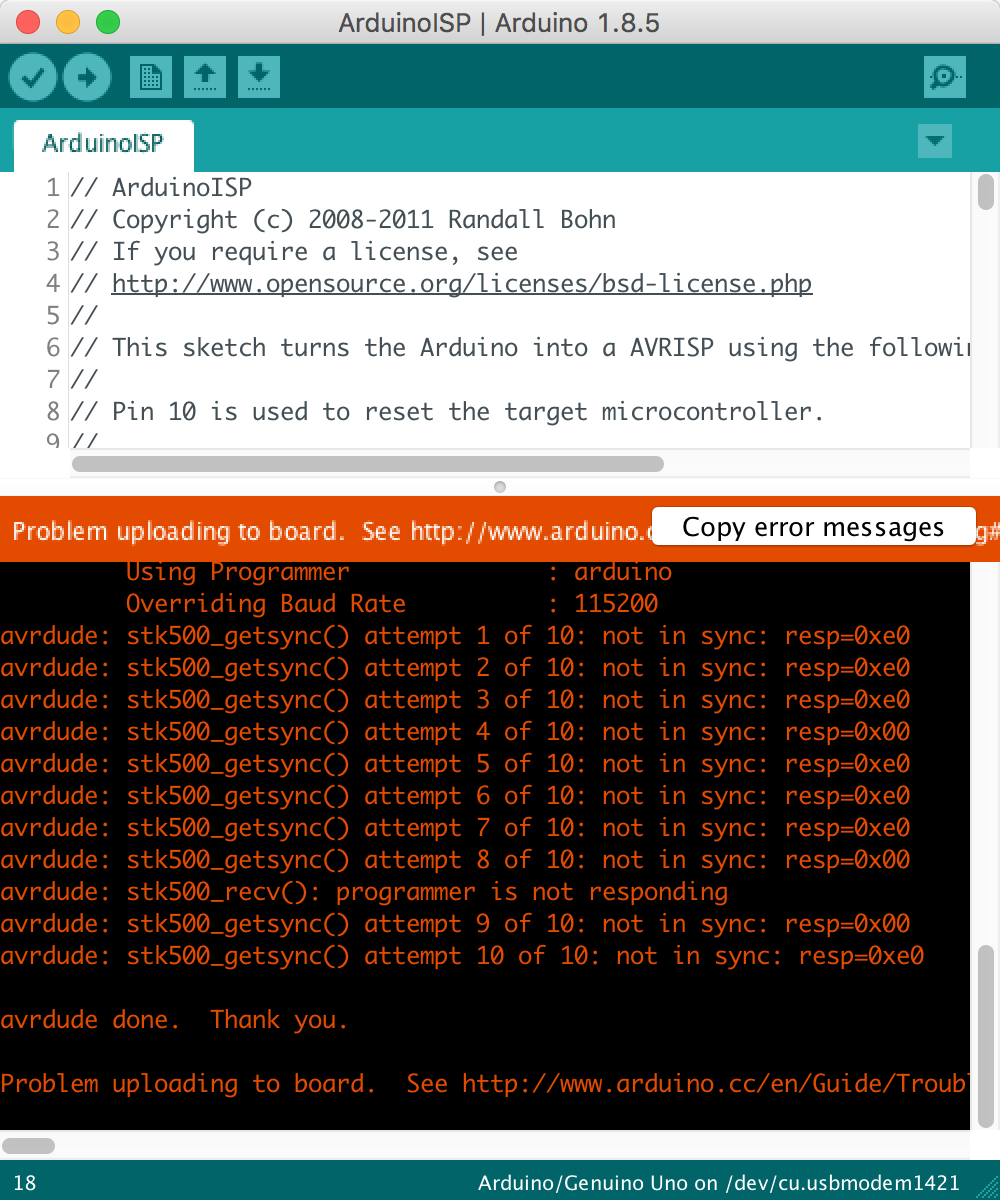
Make sure you do NOT have a capacitor connected across the RESET and GND pins on the Arduino UNO. It will prevent the Arduino UNO from resetting and thus cause the Arduino UNO to be unable to be unprogrammable.
You may get a skt500_getsync() error message which is characteristic of the capacitor across the RESET and GND problem or the settings listed above are not set properly.
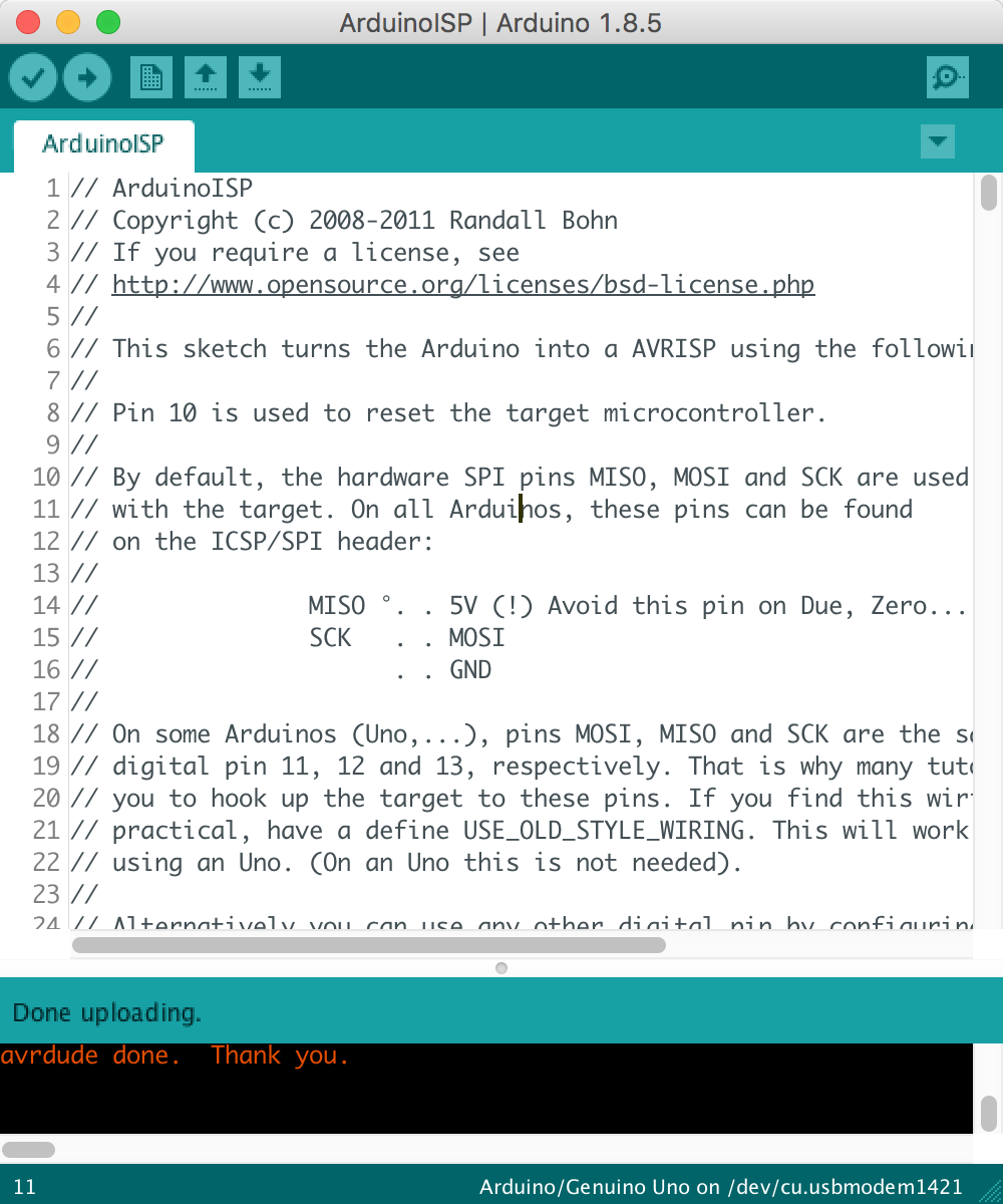
If uploading the code was successful, you will get the typical Done Uploading message.
Now the Arduino UNO is configured and is ready to program AVR microcontrollers.
You should have Arduino installed and be familiar enough to explore new Arduino based projects. Check out our Related Projects to get started making something awesome!


